This web page offers the complete text and all
illustrations for the monograph [1e] by Dr Jan Pająk,
"Advanced Magnetic Propulsion Systems" (Copyrights © 1990, ISBN 0-9597698-9-7)
disseminated via this web page free of charge
Notices:
(1)
All web pages with free offers of my monographs
and treatises that use a lot of illustrations (i.e. like
this one) are prepared in two versions. The first
version offers the text of a given publication (usually
in various formats) and has all illustrations not revealed.
Thus readers who wish to see any illustration must
click on a
(green and underlined)
link to the illustration that interests them in order
to open it. The second version of these web pages
offers the text usually in only one format (i.e. in PDF),
but displays all illustrations used in this publication
at the loading stage. So readers can see all illustrations
at once, compare these with each other, select the
one which they wish to examine in details, etc.
(2)
By the end of June 2009 all monographs and
treatises which I (i.e.
Dr Jan Pająk)
authorise, were translated into a safe and
convenient PDF format (with illustrations
included into their content). They are
offered free of charge for reading by
all interested people. Thus, I recommend
to download these publications for
yourself in such safe format PDF.
After all, in PDF my publications
are "ready to print", and additionally
to the PDF format computer viruses
cannot be attached. Unfortunately,
because of the large size of documents
caused by the inclusion of illustrations
to content of these publications, NOT
every free server with web sites of
totalizm
is able to accommodate these publications.
Therefore, in order to download the
selected publication in the PDF format,
you firstly need to find the server (address)
in the internet under which it is available
free of charge. In order to find it, you need
to check the availability of PDF format in
addresses listed for a given publication
(and web page) in "Menu 3" or in "Menu 4"
from the left margin of this web page.
(3)
Everything that in this text area of the web page
is marked with the
green colour and underlined
is actually a link to a web page that concerns the
matter named in this green colour. So if readers
wish to extend their knowledge on this matter, they
just need to click on this
green in colour and underlined
link. (But I do NOT recommend to click already
during the first reading, because it could destroy
the reader's concentration span and interrupt the
understanding of a given matter. To these pages
that are to extend the knowledge is better to reach
only during the second, or even further, reading
of a given description!)
(4)
In order to download to your computer text of
any of volumes listed below, or in order to
see/download any illustration, just
click
on the underlined
(green)
description chosen from the list below!
(5)
All illustrations from copies of monograph [1e] in the PDF
format, are collected at ends of chapters. Therefore, to
easier shift our attention during the reading from the text
to an illustration which is just analysed, it helps to keep
in the computer two copies of the monograph which we
are just reading, the first of which we open on the text
that we read directly from the screen, while the second
copy we open on the illustration which we just are analysing.
Then, with mouse, we just quickly shift (by clicking) from
the window with the text to the window with the illustration
under analysis.
(6)
The propelling devices called the "Magnocraft",
"Oscillatory Chamber", "UFOs", etc., which
are described in this monograph [1e], even more
thoroughly are also described in chapters B to F
from volumes 2 and 3 of two my other monographs, namely
[1/4] and
[1/5].
Therefore these chapters B to F from monographs
[1/4] or [1/5] provide a good technical extension
for information contained in this monograph [1e].
The same devices are also described briefly in a
number of web pages (on each web page being
presented from a different point of view), for
example on the web page named
magnocraft.htm -
which is entirely devoted to the Magnocraft,
on the web page named
oscillatory_chamber.htm -
which is entirely devoted to the Oscillatory Chamber, or in
items #D1 and #D2 of the web page named
propulsion.htm,
in items #H1 to #H3 of the web page named
tapanui.htm,
or in items #D1 to #D5 of the web page named
eco_cars.htm.
A list of web pages describing these devices is
provided below in "part #E".
(7)
Illustrations
used in this monograph [1e] are also used in
monographs [1/5], [1/4] and [2e]. Thus, if here
these illustrations come out unclear, they can
also be seen in [1/5], [1/4] or [2e].
Part #A: Free copies of
monograph [1e] in ADOBE.PDF format:
The problem with the monograph [1e]
"Advanced Magnetic Propulsion Systems"
(Copyrights © 1990, ISBN 0-9597698-9-7)
is that it is my largest monograph disseminated
in a single volume. The PDF and single copy
version of this monograph occupies around
17 MB of computer memory. Thus only the
most generous web servers are providing
the amount of memory that is required. For
this reason the single copy of monograph
[1e] in the PDF format is available only
at just a few addresses used by totalizm.
If the reader wishes to download [1e] as
a single volume, he or she needs to find
a server which have it. To find it, it suffices
just trying to download it from various
addresses provided in "Menu 3".
Here is the link to a complete copy of
[1e] - if it is available here at this address.
Click on the green (underlined) name
below and try whether it downloads from
here:
English monograph [1e], single copy format PDF
Should the entire copy of [1e] in a single
volume not be available at this address, the same
[1e] may be offered here free of charge split into
three separate volumes (after all, in such a case each
one of these volumes requires less memory to store).
Here are links to such three-volume version of the
same [1e] in the PDF format:
Volume 1 in the ADOBE (*.pdf) format.
Volume 2 in the ADOBE (*.pdf) format.
Volume 3 in the ADOBE (*.pdf) format.
Part #B: List of content of the English monograph [1e] by Dr Jan Pająk,
"Advanced Magnetic Propulsion Systems" (1990, ISBN 0-9597698-9-7):
Notice that symbols composed of a letter, dash, and a number (e.g. "A-1") provided after the
subsections' titles, are page numbers on which given subsections appear in the PDF version of [1e].
Symbols in front of subsections' titles are simply numbers of given subsections.
A. INTRODUCTION A-1
A1. The organization of this monograph A-1
A2. Reference to resource publications A-1
A3. This monograph formally proves that UFOs do exist A-2
A4. How to read this monograph A-3
A5. The history of this monograph A-4
A6. The aims of this monograph A-5
A7. Sponsorship for the building of the
Oscillatory Chamber is sought A-6
A8. Constructive criticism as a motive force for the
further development of the Theory of the Magnocraft A-7
A9. Milestone Journal articles by the author A-7
PART 1: THE PHILOSOPHICAL FOUNDATIONS B-9
B. THE PERIODIC PRINCIPLE IN THE DEVELOPMENT
OF PROPULSION SYSTEMS B-10
B1. Everything in our environment, including the formulation
of inventions, is governed by appropriate laws B-11
B2. The basics of propulsion B-11
B2.1. The working medium B-12
B2.2. The primary requirement for building
a controllable propulsion system B-13
B3. The content of the Periodic Principle B-13
B4. The first generation of the magnetic propulsion systems B-15
B4.1. The Magnocraft B-16
B4.1.1. The general design and components
of the Magnocraft B-16
B4.1.2. Flight control B-17
B4.1.3. The specifications of the Magnocraft B-18
B4.2. The second motor propulsor pair in the first
generation of magnetic propulsion systems B-19
B5. Three successive generations of magnetic propulsion systems B-19
B5.1. How the "omnibus trend" should culminate in three
conventions of the Magnocraft's operation B-20
B6. Second generation of magnetic propulsion systems,
operating in the telekinetic (teleportative) convention B-21
B6.1. Phenomenon utilized in the second generation
of magnetic propulsion systems B-21
B6.1.1. Action of the Telekinetic Effect explained
by the Concept of Dipolar Gravity B-23
B6.1.2. Summary of the Telekinetic Effect
activated technologically B-25
B6.2. Telekinetic power stations (or "free energy devices") B-26
B6.2.1. Periodic Table postulating the future
completion of telekinetic power stations B-27
B6.2.2. Review of the main types of telekinetic
power stations built so far B-29
B6.2.3. Future directions in utilization of the
Telekinetic Effect B-36
B6.3. Teleportation Vehicle as the Magnocraft
of the second generation B-37
B7. Third generation of the Magnocraft (Time Vehicles) B-41
Tables B1 and B2 B-45
Figures B1 to B10 B-47
C. EVEN IF ANTIGRAVITY EXISTED, MAGNETIC PROPULSION WOULD STILL
REMAIN THE ONLY FEASIBLE ALTERNATIVE FOR SPACECRAFT
TRAVELLING INTERSTELLAR DISTANCES C-57
C1. The antigravitational spacecraft would be impossible
to manoeuvre and difficult to stabilize C-58
C2. The manoeuvrable antigravitational spacecraft would
simply be an advanced version of contemporary rockets C-59
C3. With self rechargeable propulsion,
gravity does not affect energy consumption C-60
C4. The field of the antigravitational spacecraft
would absorb huge amounts of energy C-61
C5. For the purpose of landing, the energy of the
antigravitational field must be disposed of C-62
C6. The strong field would repel everything
from the antigravitational spacecraft C-62
C7. The forces of reaction caused by the
repulsion of other objects, would also hurl
the antigravitational craft through space C-63
C8. Antigravity would induce a number of dangers C-63
C9. Even without knowing about the Concept of Dipolar Gravity
there are no known premises suggesting any possibility
of achieving the antigravitational field C-64
C10. Summary C-64
D. THE CONCEPT OF DIPOLAR GRAVITY D-66
D1. Why the Concept of Dipolar Gravity was formulated D-67
D2. The operation of our Universe ruled by dipolar gravity D-70
D2.1. Ether the thinking substance
from the counter world D-74
D2.2. Software models (registers) of material objects D-76
D2.3. Possible gains from the mastery
of the counter world D-78
D3. The interpretation of time
in the Concept of Dipolar gravity D-78
D4. The interpretation of electromagnetic phenomena
in the Concept of Dipolar Gravity D-80
D4.1. What is a magnetic field? D-80
D5. Why, according to the Concept of Dipolar Gravity,
paranormal phenomena must display
electromagnetic character D-82
D6. Telekinesis a power source for free energy devices
and a principle of operation for Teleportation Vehicles D-83
D7. The model of the brain as an input output device D-86
D8. ESP a key to instant benefits from the counter world D-90
D8.1. Perfect Data Base (PDB) as a theoretical model of ESP D-93
D8.2. How to develop a simplest
pendulum assisted ESP technique D-95
D9. How the Concept of Dipolar Gravity
explains some mysterious phenomena D-96
D10. How the Concept of Dipolar Gravity
merges science with religion D-99
D10.1. The Universe as a whole possesses its own intellect D-99
D10.2. Moral laws D-101
D10.3. Consistency the measure
of intellectual perfection D-104
D11. An experimental proof for the
existence of the counter world D-104
D12. To conclude D-107
D13. Reference publications D-107
Figures D1 to D8 D-108
E. PHILOSOPHICAL REQUIREMENTS
FOR GIVING RECOGNITION TO NEW IDEAS E-115
E1. Everything is possible: we only need
to find out how to achieve it E-116
E2. All facts are equal each of them
deserves the same consideration E-117
E3. All statements of others are true
unless they are proven to be untrue E-118
E4. Everything can be improved further E-120
E5. Knowledge is responsibility E-121
E6. What is totalizm? E-122
Figure E1 E-124
PART 2: THEORY OF THE MAGNOCRAFT F-125
F. THE OSCILLATORY CHAMBER F-126
F1. Why there is a necessity to replace the electromagnet
by the Oscillatory Chamber F-126
F2. The principle of operation of the Oscillatory Chamber F-128
F2.1. The electrical inertia of an inductor as the
motive force for oscillations in a conventional
oscillatory circuit with a spark gap F-128
F2.2. In the modified oscillatory circuit with a spark gap,
the inductance of a stream of sparks replaces
the electrical inertia of an inductor F-129
F2.3. The combination of two modified circuits
forms an "Oscillatory Chamber"
producing a bipolar magnetic field F-131
F3. The future appearance of the Oscillatory Chamber F-132
F4. The condition under which the sparks will oscillate
within the Oscillatory Chamber F-133
F4.1. Resistance of the Oscillatory Chamber F-133
F4.2. Inductance of the Oscillatory Chamber F-133
F4.3. Capacitance of the Oscillatory Chamber F-134
F4.4. The "sparks' motivity factor" and its interpretation F-135
F4.5. Condition for the oscillatory response F-135
F5. How the Oscillatory Chamber eliminates
the drawbacks of electromagnets F-136
F5.1. Mutual neutralization of the two
opposite electro magnetic forces F-136
F5.2. Independence of the magnetic field production from
the continuity and efficiency of the energy supply F-137
F5.3. Elimination of energy loss F-138
F5.4. Releasing the structure of the chamber from
the destructive action of electric potentials F-140
F5.5. Amplifying control of the period of field pulsation F-140
F6. Advantages of the Oscillatory Chamber over electromagnets F-141
F6.1. Formation of the "twin chamber capsule"
able to control the output
without altering the energy involved F-142
F6.2. Formation of the "spider configuration" F-144
F6.3. The non attraction of ferromagnetic objects F-145
F6.4. Three dimensional transformation of energy F-146
F6.5. Perpetual oscillating a unique electromagnetic
phenomenon allowing the Oscillatory Chamber
to absorb unlimited amounts of energy F-146
F6.6. Function as an enormously
capacious accumulator of energy F-147
F6.7. Simplicity of production F-148
F7. Advancements in the practical completion of
the Oscillatory Chamber F-148
F7.1. Experimental devices F-149
F7.2. Stages, goals, and ways of their achieving in
the experimental building of the Oscillatory Chamber F-150
F7.3. The author's policy of the public ownership
of the Oscillatory Chamber principles F-152
F8. The energy conservation and energy production potentials
of the Oscillatory Chamber F-153
F8.1. Characteristics of the first period (change over)
of the chamber's implementation F-154
F8.2. Characteristics of energy management during the second,
stable period of the Oscillatory Chamber's utilization F-154
F9. Future applications of the Oscillatory Chamber F-156
F10. Monographs describing the Magnocraft,
the Oscillatory Chamber and other corresponding devices F-157
F11. Symbols used in chapter F F-159
Table F1 and Figures F1 to F10 F-160
G. THE MAGNOCRAFT G-171
G1. The magnetic propulsor G-172
G1.1. The principle of tilting the magnetic axis
in a Magnocraft's propulsor G-173
G1.2. The propulsion unit G-174
G1.3. Using propulsors as searchlights G-175
G2. The shell of the Magnocraft G-175
G2.1. Terminology describing various parts
of the Magnocraft's shell G-176
G2.2. The Magnocraft's compartments G-177
G2.3. The Magnocraft's facilities G-178
G2.4. Materials for the Magnocraft's shell G-178
G2.4.1. The electrodynamic model
of magnetoreflectiveness G-179
G3. Shapes of the coupled Magnocraft G-179
G3.1. The six classes of the Magnocraft arrangements G-180
G3.1.1. Flying complexes G-181
G3.1.2. Semi attached configurations G-182
G3.1.3. Detached configurations G-183
G3.1.4. Carrier platforms G-183
G3.1.5. Flying systems G-184
G3.1.6. Flying clusters G-184
G3.2. The principles of coupling and decoupling G-186
G3.3. The hydraulic substance filling the space
between the craft ("angel's hair") G-187
G3.4. The black bars of the magnetic field G-188
G4. The conditions defining the shape of the Magnocraft's shell G-188
G4.1. The condition of equilibrium between
the thrust and stabilization forces G-189
G4.2. The basic condition for the force stability of the
structure of a craft which uses magnetic propulsors G-190
G4.3. The condition for expressing the "K" factor
by the ratio of outer dimensions G-191
G4.4. The condition for optimum coupling
into flying systems G-192
G4.5. The condition under which the flanges coincide G-192
G4.6. Types of Magnocraft G-193
G4.7. Identifying the types of Magnocraft G-194
G4.8. The magnetic framework G-195
G5. The magnetic field of the Magnocraft G-195
G5.1. The starting flux G-195
G5.2. The naming of the magnetic poles G-198
G5.3. The effective length of the Oscillatory Chamber
and the net magnetic force G-197
G5.4. The determination of the value for the starting flux G-198
G5.5. The energy of the Magnocraft's field G-199
G5.6. The energy of the Magnocraft's field
is self rechargeable G-200
G5.7. Why the Earth's magnetic field
should not be called "weak" G-200
G5.8. The Earth's magnetic field
is able to carry out technically useful work G-201
G6. The manoeuvring of the Magnocraft G-201
G6.1. Ascent, hovering, and descent G-202
G6.2. Meridional flights G-202
G6.3. Latitudinal flights G-203
G6.3.1. An experiment showing the existence
of the latitudinal thrust force G-203
G6.3.2. The deduction that explains the principles
of the latitudinal thrust force formation G-203
G6.3.3. How to determine the direction of the
thrust force created by the magnetic whirl
(the "rolling sphere rule") G-204
G6.4. The rotation of the Magnocraft G-205
G7. The magnetic whirl G-206
G7.1. The magnetic circuits in the Magnocraft G-206
G7.2. Creation of a magnetic whirl G-207
G7.3. The ionic picture of a whirl G-208
G8. Three modes of the Magnocraft's operation G-209
G8.1. Visual recognition of the mode G-210
G8.2. The SUB system for indicating the Magnocraft's
mode of operation G-211
G9. The properties of the Magnocraft G-212
G9.1. The properties of the Magnocraft during the
magnetic whirl mode of operation G-212
G9.1.1. Properties of the tunnels made in rocks
by the Magnocraft G-213
G9.2. The properties of the Magnocraft during the
throbbing mode of operation G-215
G9.3. Humming noises appearing in both the magnetic
whirl and throbbing modes of operation G-215
G9.4. The properties of the Magnocraft
during the magnetic lens mode of operation G-216
G9.4.1. The magnetic lens action
in ascending Magnocraft G-217
G10. The landing sites of the Magnocraft G-217
G10.1. Environmental damage caused by the landed Magnocraft G-218
G10.2. Three main classes of the Magnocraft's landings G-221
G10.3. The landing sites for the magnetic circuits
looped under the ground G-222
G10.3.1. Determination of the Magnocraft's dimensions
from the scorch marks left at landing sites G-223
G10.4. The landing sites with magnetic circuits
looped along the surface of the ground G-225
G10.5. The landing sites for circuits looped in the air G-225
G10.6. The landing sites formed by
arrangements of the Magnocraft G-226
G11. Explosion sites of the Magnocraft G-226
G12. Summary of the attributes of the Magnocraft G-229
G13. Military aspects of the Magnocraft G-233
G13.1. Use of the Magnocraft as a
weapons platform or transportation facility G-233
G13.2. Use of the Magnocraft as a
selectively acting weapon G-234
Tables G1 to G3 and Figures G1 to G42 G-236
H. PERSONAL PROPULSION H-282
H1. The standard garment of Personal Propulsion H-282
H2. A special version of Personal Propulsion
with cushions around the hips H-283
H3. The garment with main propulsors in epaulets H-283
H4. Principles of operation of magnetic Personal Propulsion H-284
H5. The attributes of Personal Propulsion H-285
Figures H1 to H4 H-287
I. THE FOUR PROPULSOR SPACECRAFT I-291
I1. The general design of the Four Propulsor Spacecraft I-291
I2. The operation of the Four Propulsor Spacecraft I-292
I3. The properties of the Four Propulsor Spacecraft I-293
I4. Identification of the type of Four Propulsor Spacecraft I-294
Figures I1 to I2 I-295
PART 3: THE EVIDENCE CONFIRMING THE VALIDITY
OF THE THEORY OF THE MAGNOCRAFT J-297
J. FORMAL PROOF THAT "UFOs ARE ALREADY OPERATIONAL MAGNOCRAFT" J-298
J1. Principles of selecting the relevant UFO evidence J-300
J2. Matching of the Magnocraft's attributes
with those observed in UFOs J-302
J2.1. The observed shapes of solo flying vehicles J-302
J2.1.1. The vision distorting factors J-303
J2.2. The observable arrangements of coupled vehicles J-304
J2.3. The absence of mechanically co operating parts J-306
J2.4. The predetermined (Magnocraft like)
location of propulsors J-306
J2.5. The utilization of magnetic interactions
for producing the propelling forces J-307
J2.5.1. Why the Magnocraft's principles could
not be formulated 40 years earlier J-308
J2.6. The formation of a magnetic whirl J-309
J2.7. The ability to change the mode of the UFO's operation J-309
J2.8. The induction of electric currents J-311
J2.9. The emission of various light signals J-311
J2.10. The interference with electromagnetic radiation J-313
J2.11. The ability to control the
resources of the UFO's energy J-315
J2.12. The magnetic manner of flying which
contradicts laws of hydromechanics J-316
J3. Concluding the reasoning and evidence from this chapter J-317
J4. Chapter J reference material J-320
Figures J1 to J34 J-321
K. THE VALIDATION OF THE CONCEPT OF DIPOLAR GRAVITY K-355
K1. Premises for the telepathic beacon system
installed on Earth K-355
K2. Sightings of Teleportation Vehicles in operation K-357
K3. The evidence confirming the existence of Time Vehicles K-359
Figures K1 to K4 K-363
L. EVIDENCE CONFIRMING THE VALIDITY OF THE OSCILLATORY CHAMBER L-367
L1. Sightings and photographs of Oscillatory Chambers
used in UFO propulsors L-367
L1.1. Columns of magnetic field yield from UFO propulsors
are square in the cross section L-368
L1.2. Outlets of UFO propulsors are square and reveal gold
or yellow bands of electric sparks rotating inside L-369
L1.3. Twin chamber capsules formed from two Oscillatory
Chambers are frequently observed in UFOs
and even photographed L-370
L1.4. Oscillatory Chambers have been seen on the decks
of UFOs as described by numerous abductees L-371
L1.5. Indirect confirmations that UFOs
use Oscillatory Chambers L-373
L2. Material evidence left by UFO Oscillatory Chambers L-374
L3. Ancient descriptions of the Oscillatory Chamber L-374
L4. Conclusion L-377
L5. Chapter L reference material L-377
Figures L1 to L7 L-379
M. THE MATERIAL EVIDENCE AVAILABLE THAT CONFIRMS
THE LONGSTANDING USE OF MAGNOCRAFT TYPE UFOs M-386
M1. Material evidence on UFO landing sites M-387
M1.1. All three known types of landing sites are
formed by visiting extraterrestrial vehicles M-387
M1.2. The value of the Cosmic Cubit can be
determined from UFO landing sites M-388
M1.3. The diameters of landing sites confirm the existence
of eight basic types of extraterrestrial vehicles M-390
M1.4. Some marks left on the ground document the
landing of entire configurations of UFOs
(including flying systems) M-391
M1.5. Why UFO landing sites could not be formed by the
growth of mushrooms or by any other natural cause M-391
M1.6. There is a critical landing duration
after which sites become permanent M-394
M1.7. More that else we can learn from UFO landing sites M-394
M2. Long, straight, geometrically shaped underground
tunnels material evidence of the ancient operation
of the Magnocraft M-396
M3. UFO explosion sites M-398
M3.1. The Tapanui Crater M-399
M3.2. The Tunguska Explosion M-405
M3.3. What can be learned from both explosion sites
(i.e. Tapanui and Tunguska) M-408
M4. Fragments of UFO vehicles found on Earth M-410
Figures M1 to M30 M-411
N. SIGHTINGS OF UFONAUTS WHO USE MAGNETIC PERSONAL PROPULSION N-441
N1. The characteristic appearance of
the wearers of personal propulsion N-441
N2. The extraordinary abilities of UFOnauts
wearing personal propulsion-garments N-442
N3. The scorched footprints left by
personal propulsion of a UFOnaut N-443
N4. The consequences of the sighting of
personal propulsion of UFOnauts N-444
Figures-N1-to-N6 N-446
O. CONTEMPORARY SIGHTINGS OF FOUR-PROPULSOR UFOs O-452
O1. Classic sightings of four propulsor UFOs O-452
O2. Photographs of four propulsor UFOs O-454
O3. Concluding this chapter O-454
Figures O1 to O3 O-455
P. HOW TO ORGANIZE EDUCATIONAL COURSES DEDICATED TO
"EXPLAINING THE UNEXPLAINED" P-458
Figures P1 to P2 P-460
Q. ABOUT THE AUTHOR Q-462
Illustrations:
If the reader downloaded for himself this publication
in the PDF format, then it already contains all illustrations
discussed in its content. However, some photographs
and drawings included into its content, sometimes
needed to be decreased in size, to fit into single
pages of paper of the A4 format. Thus selected
details on photographs and drawings already
included into the PDF format may NOT be visible
clearly enough. For this reason electronic version
of all these photographs and drawings used in
my publications are also made available in the
internet - so that everyone could analyse them
thoroughly in internet, or download to own computer.
This in turn allows to enlarge these illustrations
to any size required - allowing the detailed
analysis and viewing. Furthermore, internet
copies of all illustrations used in this publication
can also be downloaded and included into
copies of this publication disseminated in source
formats such as DOC, WP5, or ZIP (i.e. formats
other than PDF). After all, these other formats
NOT always have illustrations included into them.
* * *
Please notice that NOT all servers (addresses)
contain all illustrations displayed on this web page.
Thus, if under this address any illustration is NOT
shown (i.e. if you can only see the frame of that
illustration), then you need to jump at the same
web page but available under a different address
indicated in "Menu 3" or in "Menu 4", and see this
illustration over there.
Part #C: Illustrations for monograph [1e] (i.e. in English), in formats *.gif or *.jpg.
Notice that you can see the
enlargement
of each illustration from this web site.
For this, it suffices to click on a
(green and underlined link marked "[1e] Figure ?")
which is to open a separate windows with
that illustration. Furthermore, most of the
internet browsers that you may use,
including the popular "Internet Explorer",
allow also to download
each illustration to your own computer,
where it can be looked at, reduced or
enlarged to the size that you may want,
or printed with your own graphical software.
* * *
The Polish version [1p] of this monograph uses different illustrations than the English version [1e].
* * *
Captions for each illustrations are intentionally short on this web page - describing only key points of given illustrations.
The full description of each illustration can be found in captions from the PDF text of monograph [1e].
Chapter L:
 [1e] Figure L1 (a): Detached configuration of two UFOs. (a) The external appearence of such configuration. [1e] Figure L1 (a): Detached configuration of two UFOs. (a) The external appearence of such configuration.
 [1e] Figure L1 (b): A vertical cross-section through such a UFO. [1e] Figure L1 (b): A vertical cross-section through such a UFO.
 [1e] Figure L1 (c): A whole photo showing the detached configuration. [1e] Figure L1 (c): A whole photo showing the detached configuration.
 [1e] Figure L1 (d): Enlargement of the vehicle - it clearly shows the "black bars" running between side propulsors. [1e] Figure L1 (d): Enlargement of the vehicle - it clearly shows the "black bars" running between side propulsors.
 [1e] Figure L1 (e): The same configuration a while later. [1e] Figure L1 (e): The same configuration a while later.
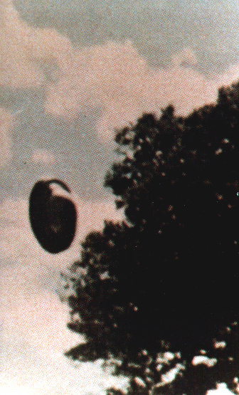
 [1e] Figure L2 (a): "Black bars" in a spool-shaped UFO. [1e] Figure L2 (a): "Black bars" in a spool-shaped UFO.
 [1e] Figure L2 (b): A reconstruction of the witness of a spool-shaped UFO type K3, Brazil, 1969. [1e] Figure L2 (b): A reconstruction of the witness of a spool-shaped UFO type K3, Brazil, 1969.
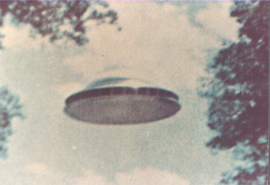
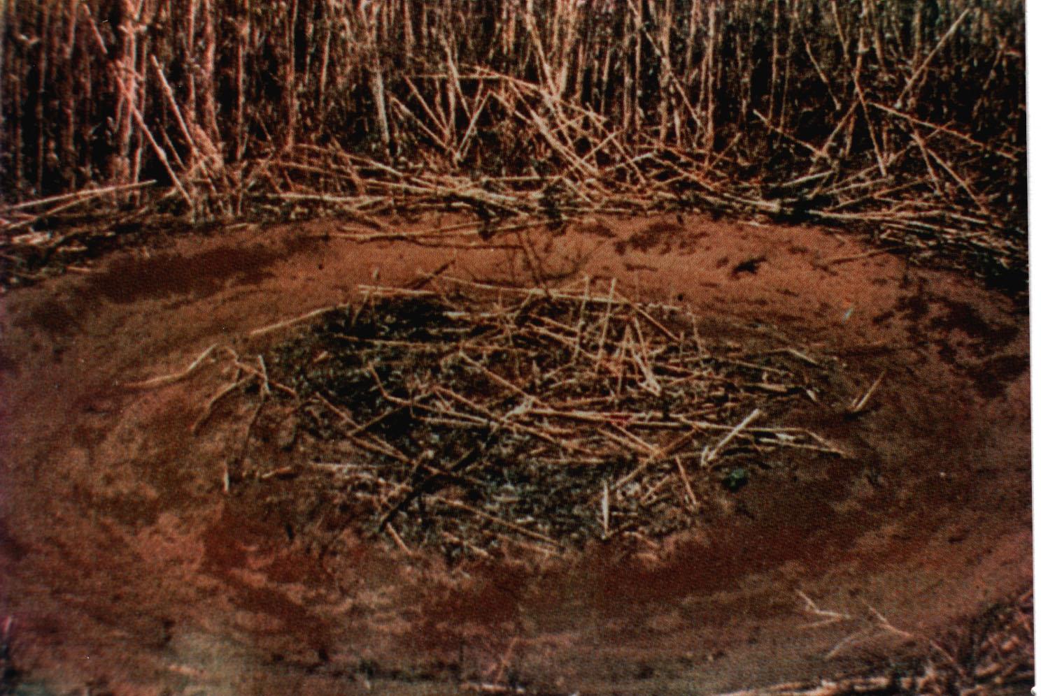
 [1e] Figure L3: A UFO's twin-chamber capsule scorched in grass, exactly as shown in Figure F5 - outer chamber flux domination. [1e] Figure L3: A UFO's twin-chamber capsule scorched in grass, exactly as shown in Figure F5 - outer chamber flux domination.
 [1e] Figure L4: A drawing of the day-time twin chamber capsule visible in an ascending UFO, exactly as shown in Figure F5 - outer chamber flux domination. [1e] Figure L4: A drawing of the day-time twin chamber capsule visible in an ascending UFO, exactly as shown in Figure F5 - outer chamber flux domination.
 [1e] Figure L4 (b): Colour photograph of a UFO capsule during daylight (inner flux prevailence). [1e] Figure L4 (b): Colour photograph of a UFO capsule during daylight (inner flux prevailence).
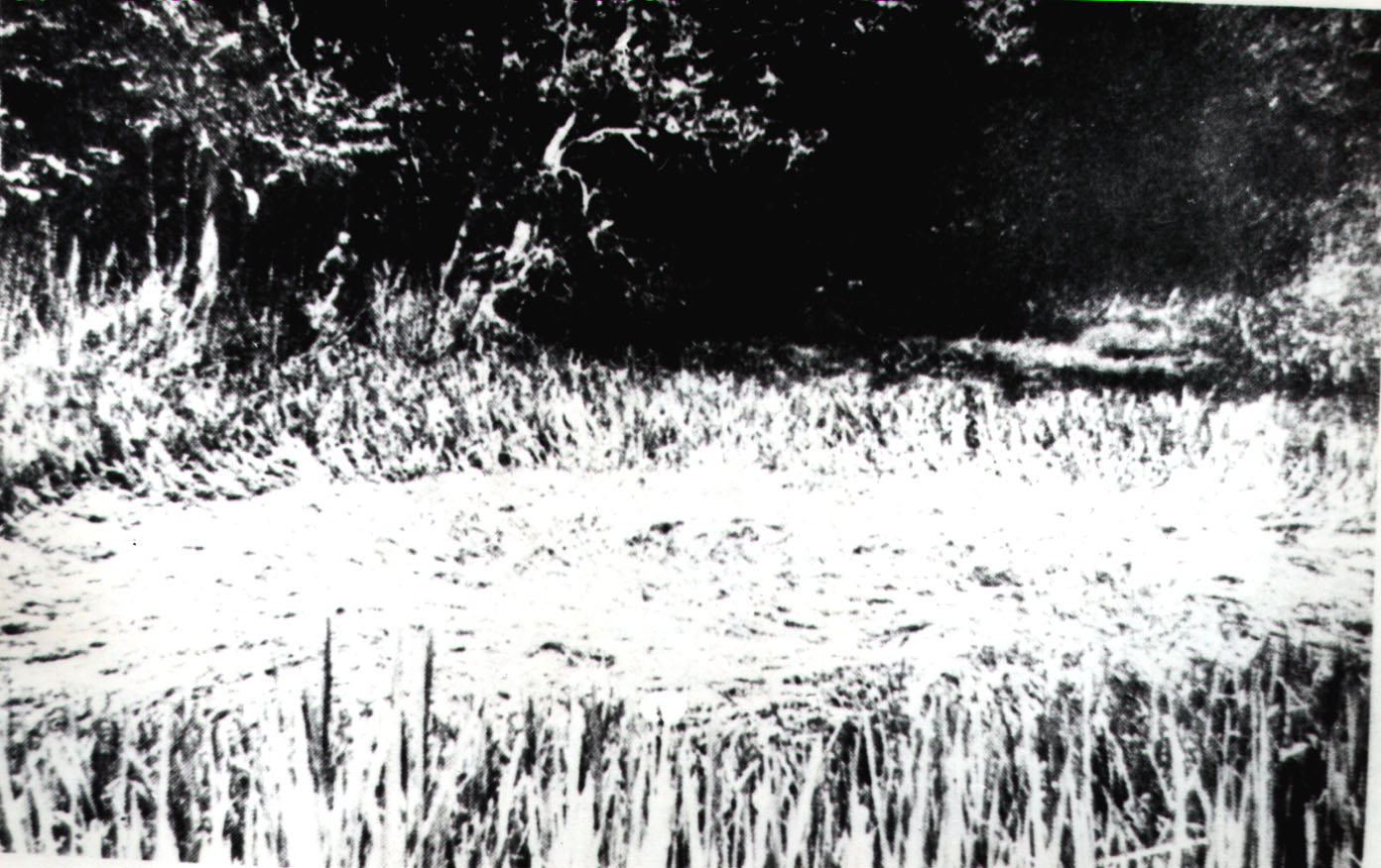
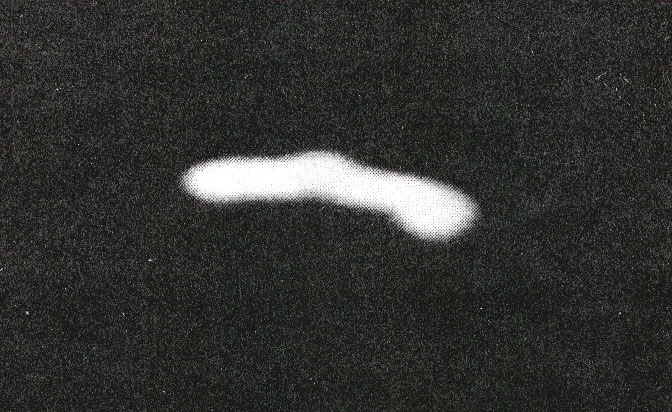 [1e] Figure L5: Night photograph of a UFO capsule (outer flux prevailence). [1e] Figure L5: Night photograph of a UFO capsule (outer flux prevailence).
 [1e] Figure L6 (left): Oscillatory Chambers seens on UFO decks. (left) The predicted appearence of such a chamber. [1e] Figure L6 (left): Oscillatory Chambers seens on UFO decks. (left) The predicted appearence of such a chamber.
 [1e] Figure L6 (right): Observed appearence of a real Oscillatory Chamber from deck of a UFO. [1e] Figure L6 (right): Observed appearence of a real Oscillatory Chamber from deck of a UFO.
 [1e] Figure L7: An ancient plan for an Oscillatory Chamber?. [1e] Figure L7: An ancient plan for an Oscillatory Chamber?.
Chapter M:
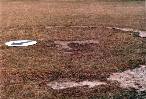
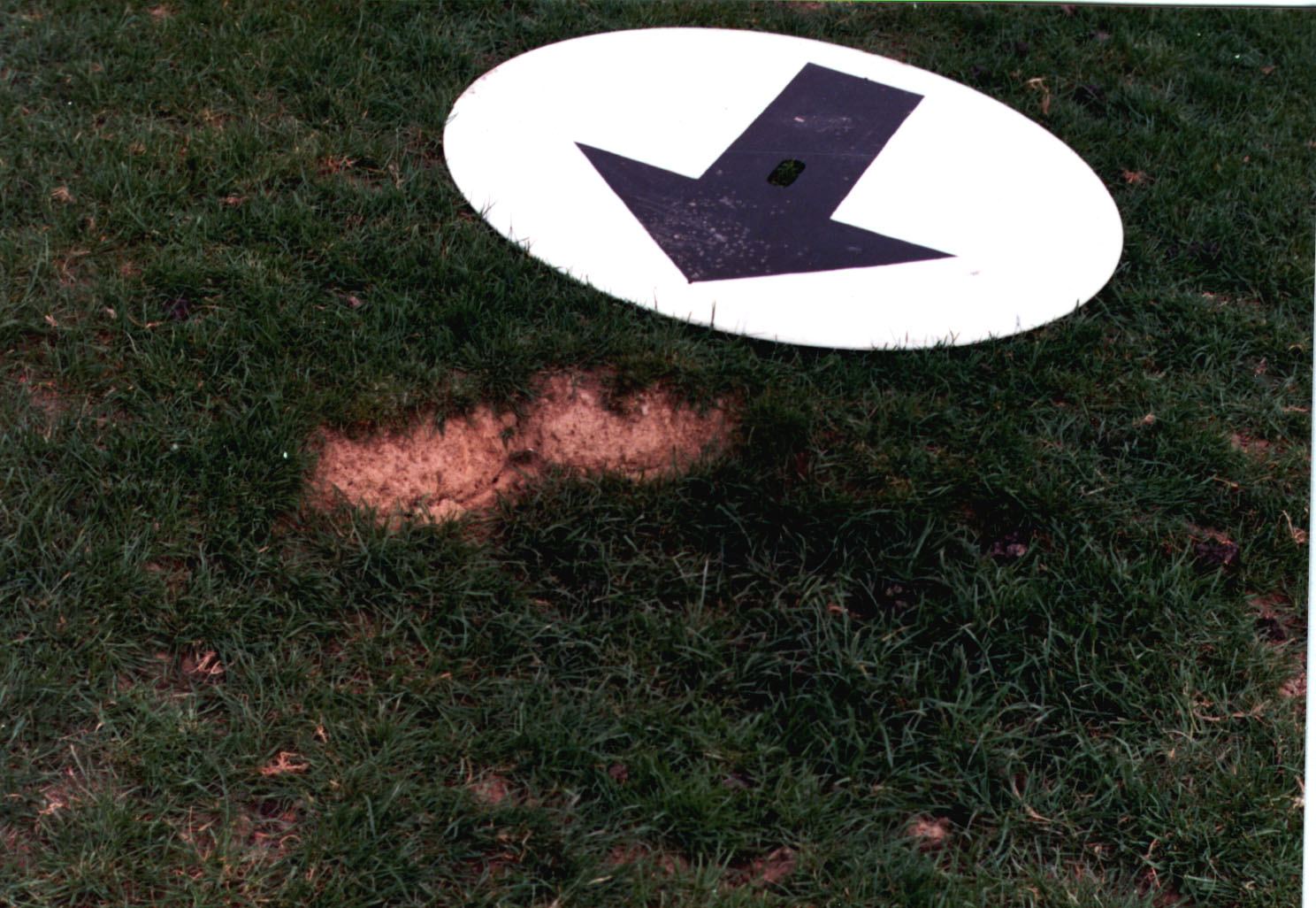
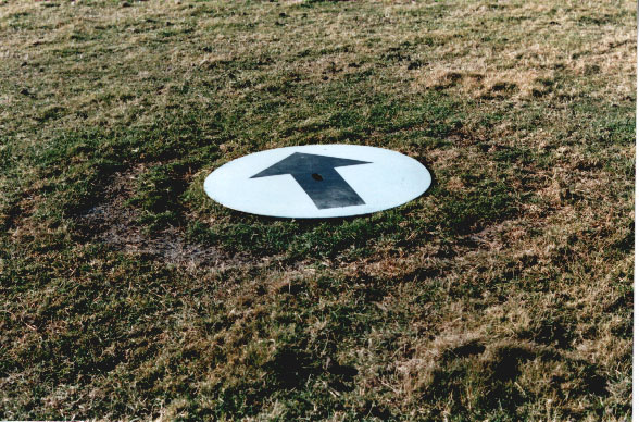
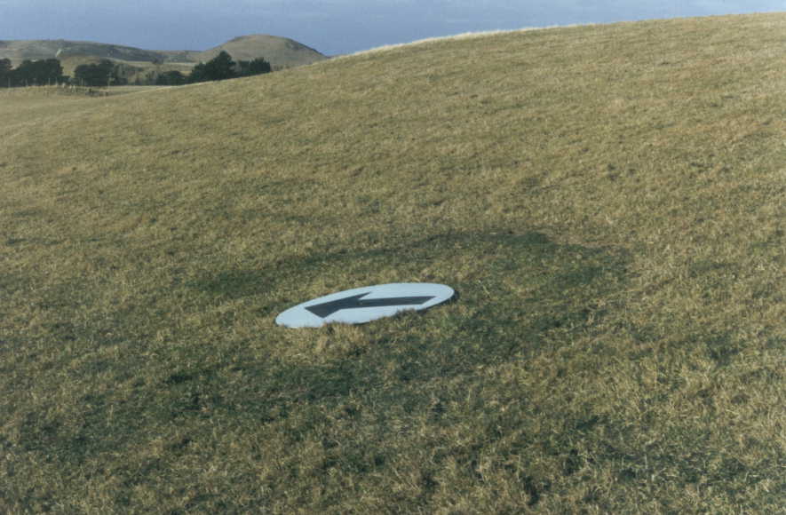
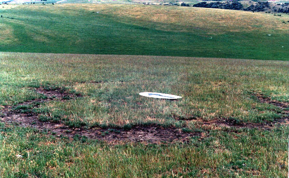
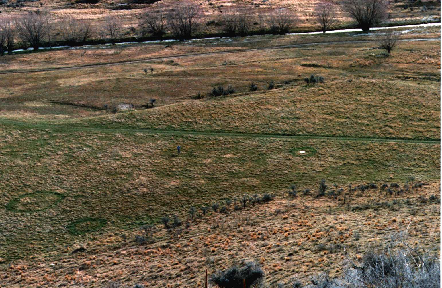
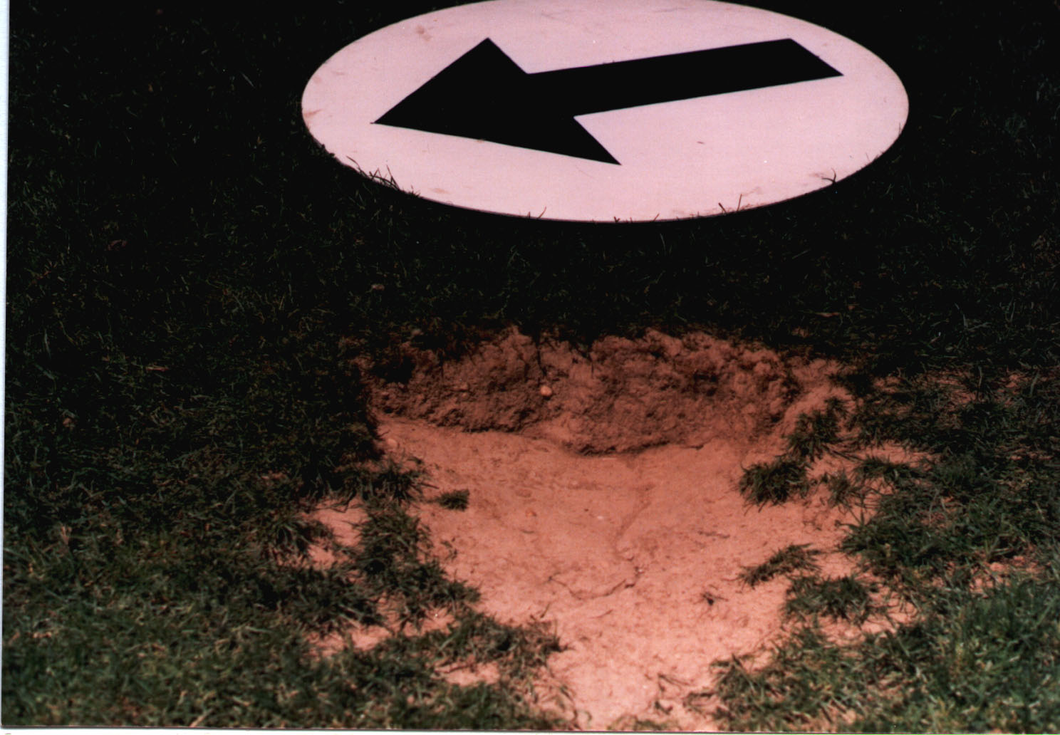 [1e] Figure M1 (up): An imprint of a leg from a K5 type UFO that landed in Maitland, New Zealand. (The wite disk is exactly 1 meter in diameter, while its arrow is pointing North). [1e] Figure M1 (up): An imprint of a leg from a K5 type UFO that landed in Maitland, New Zealand. (The wite disk is exactly 1 meter in diameter, while its arrow is pointing North).
 [1e] Figure M1 (down): One of four imprints of legs from K6 type UFO. [1e] Figure M1 (down): One of four imprints of legs from K6 type UFO.
Notice that because of the large size of this illustration, it cannot be shown on web sites *.50megs.com that limit the size of a file to 250 KB. You may see this illustration on web sites *.20m.com.
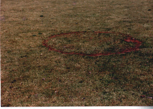 [1e] Figure M2 (upper): A landing of K3 type UFO composed of one ring and a central scorching. [1e] Figure M2 (upper): A landing of K3 type UFO composed of one ring and a central scorching.
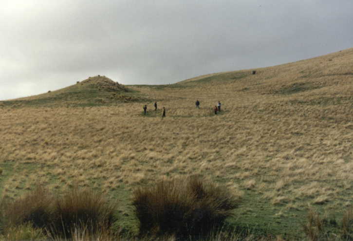
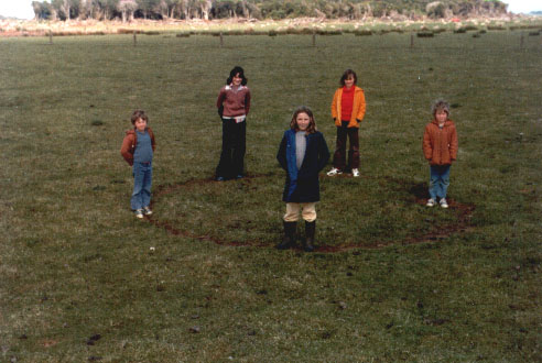 [1e] Figure M2 (lower): Children standing on this UFO landing (to give some idea about its size). [1e] Figure M2 (lower): Children standing on this UFO landing (to give some idea about its size).
 [1e] Figure M3 (up): A K5 type UFO landing scorched in the throbbing mode of operation - aclose up.(Maitland, New Zealand). [1e] Figure M3 (up): A K5 type UFO landing scorched in the throbbing mode of operation - aclose up.(Maitland, New Zealand).
 [1e] Figure M3 (down): The same K5 type UFO landing site photographed from a distance. [1e] Figure M3 (down): The same K5 type UFO landing site photographed from a distance.
 [1e] Figure M4 (up): The UFO landing site at Ngatea, New Zealand. [1e] Figure M4 (up): The UFO landing site at Ngatea, New Zealand.
 [1e] Figure M4 (down): The UFO landing at Tooligie Hill, Australia. [1e] Figure M4 (down): The UFO landing at Tooligie Hill, Australia.
 [1e] Figure M5 (up): A landing of George Pedley, Tully, Queensland. [1e] Figure M5 (up): A landing of George Pedley, Tully, Queensland.
 [1e] Figure M5 (down): A landing in Nourradons, France. [1e] Figure M5 (down): A landing in Nourradons, France.
 [1e] Figure M6 (up): A dounble-ring site by a K6 UFO in Waikoikoi, New Zealand. [1e] Figure M6 (up): A dounble-ring site by a K6 UFO in Waikoikoi, New Zealand.
 [1e] Figure M6 (down): A double-ring landing by K6 UFO in Palmerston, new Zealand. [1e] Figure M6 (down): A double-ring landing by K6 UFO in Palmerston, new Zealand.
 [1e] Figure M7 (upper): A photo of a UFO landing composed of two concentric rings. [1e] Figure M7 (upper): A photo of a UFO landing composed of two concentric rings.
 [1e] Figure M7 (lower): An elliptical landing of K3 type UFO from Genmell's silage paddock. [1e] Figure M7 (lower): An elliptical landing of K3 type UFO from Genmell's silage paddock.
 [1e] Figure M8 (high): A photo of landing of K4 UFOs in Waikoikoi, which shows soil sampling. [1e] Figure M8 (high): A photo of landing of K4 UFOs in Waikoikoi, which shows soil sampling.
 [1e] Figure M8 (lower): A photo of landing of K4 UFOs which document the binary progression in sizes of UFOs (i.e. the fact that each bigger type of UFOs is twice as big as previous type). [1e] Figure M8 (lower): A photo of landing of K4 UFOs which document the binary progression in sizes of UFOs (i.e. the fact that each bigger type of UFOs is twice as big as previous type).
 [1e] Figure M9 (up): A K5 UFO landing in Palmerston, New Zealand - close up. [1e] Figure M9 (up): A K5 UFO landing in Palmerston, New Zealand - close up.
 [1e] Figure M9 (down): A distant view of the same K5 UFO landing. [1e] Figure M9 (down): A distant view of the same K5 UFO landing.
 [1e] Figure M10 (up): A K7 UFO landing at "Shellrock Farm", Weka Pass. [1e] Figure M10 (up): A K7 UFO landing at "Shellrock Farm", Weka Pass.
 [1e] Figure M10 (down): A K7 UFO loanding in Chapman's paddock, Goodwood, New Zealand. [1e] Figure M10 (down): A K7 UFO loanding in Chapman's paddock, Goodwood, New Zealand.
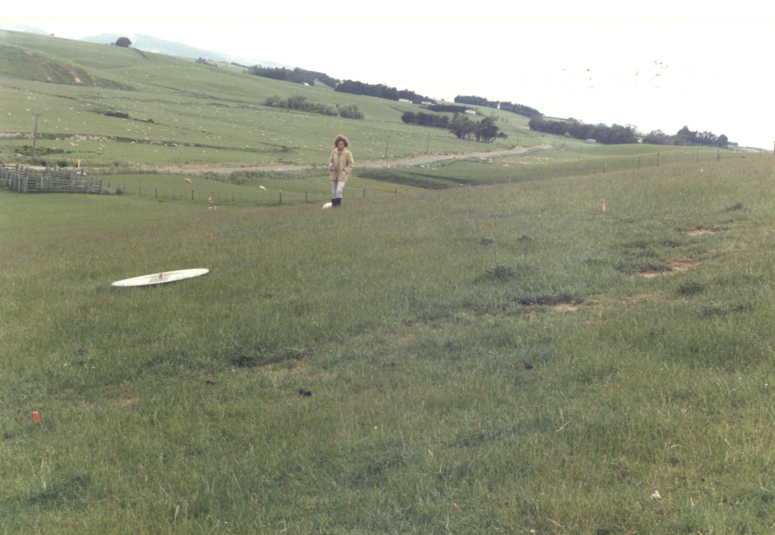
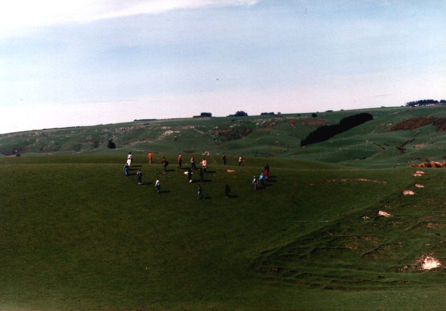
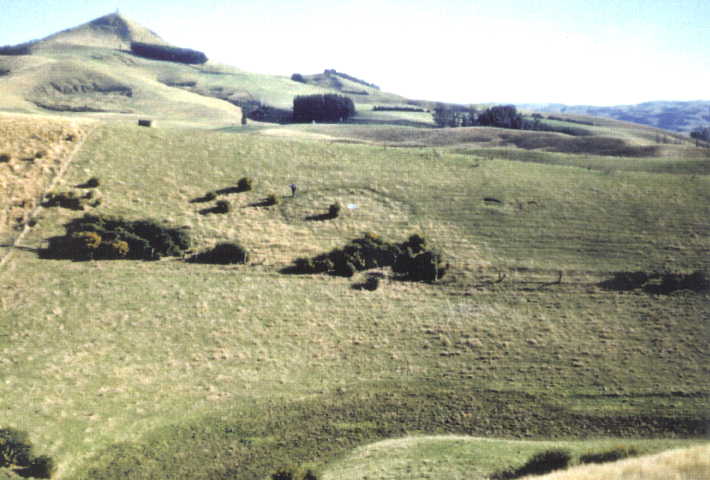
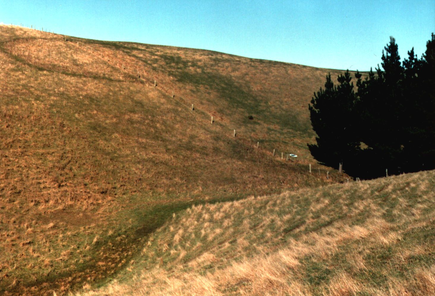
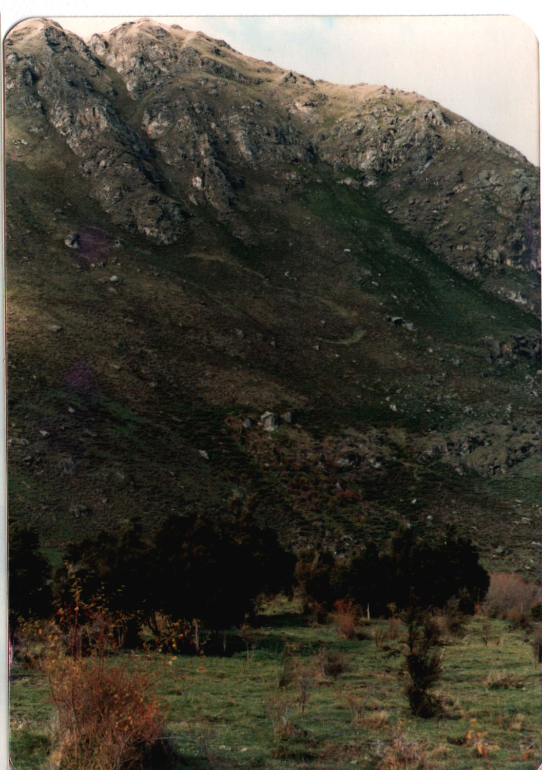
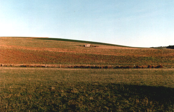
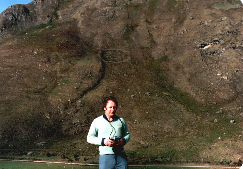 [1e] Figure M11: A K8 type UFO landing in Glendhu Bay, Wanaka. (The UFO landing is that circle of burned vegetation visible just above my head on the slope of the mountain. In spite that on the photograph it look rather small, in reality it is almost 100 meters in diameter.) [1e] Figure M11: A K8 type UFO landing in Glendhu Bay, Wanaka. (The UFO landing is that circle of burned vegetation visible just above my head on the slope of the mountain. In spite that on the photograph it look rather small, in reality it is almost 100 meters in diameter.)
 [1e] Figure M12 (a): Examples of landings of flying systems of UFOs. A single ceel of a flying system. [1e] Figure M12 (a): Examples of landings of flying systems of UFOs. A single ceel of a flying system.
 [1e] Figure M12 (b): Four-Clover landing of a single cell of a flying system. [1e] Figure M12 (b): Four-Clover landing of a single cell of a flying system.
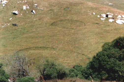
 [1e] Figure M12 (c): An aerial view of a K3 single cell of UFOs from Roxburgh. [1e] Figure M12 (c): An aerial view of a K3 single cell of UFOs from Roxburgh.
 [1e] Figure M12 (d): A closeup of the same single cell of K3 UFOs landing from Roxburgh. [1e] Figure M12 (d): A closeup of the same single cell of K3 UFOs landing from Roxburgh.
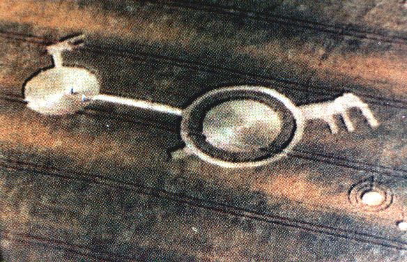 [1e] Figure M13 (up): Landing sites flatten by flying clusters of UFOs. Crop circles from K6 type of UFOs, England. The exact configuration of K6 vehicles which formed this crop circle is shown in Figure F13 from monograph [1/4e], and also in Figure G17 from this monograph [1e]. [1e] Figure M13 (up): Landing sites flatten by flying clusters of UFOs. Crop circles from K6 type of UFOs, England. The exact configuration of K6 vehicles which formed this crop circle is shown in Figure F13 from monograph [1/4e], and also in Figure G17 from this monograph [1e].
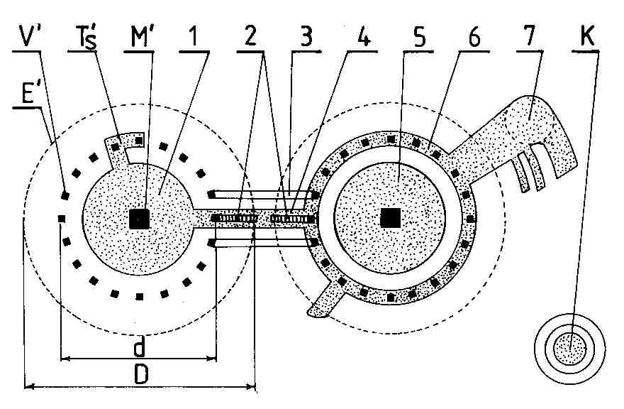 [1e] Figure M13 (down): Interpretation of the UFO landing site shown in the previous part (a) of this Figure. Descriptions of subsequent symbols from this drawing are provided in captions for illustrations from monographs [2e] and [1e], and also in the text of monographs [2e] and [1e]. [1e] Figure M13 (down): Interpretation of the UFO landing site shown in the previous part (a) of this Figure. Descriptions of subsequent symbols from this drawing are provided in captions for illustrations from monographs [2e] and [1e], and also in the text of monographs [2e] and [1e].
 [1e] Figure M14 (up): Permanent UFO landings - the oldest UFO landing noticed around 1920 (but photographed in 1987). [1e] Figure M14 (up): Permanent UFO landings - the oldest UFO landing noticed around 1920 (but photographed in 1987).
 [1e] Figure M14 (down): Mushrooms on a UFO landing site. [1e] Figure M14 (down): Mushrooms on a UFO landing site.
 [1e] Figure M15 (up): A pine tree broken by a hovering UFO type K5 (a distant view). [1e] Figure M15 (up): A pine tree broken by a hovering UFO type K5 (a distant view).
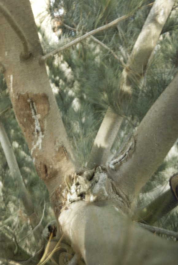 [1e] Figure M15 (down): Close up of the broken pine. [1e] Figure M15 (down): Close up of the broken pine.
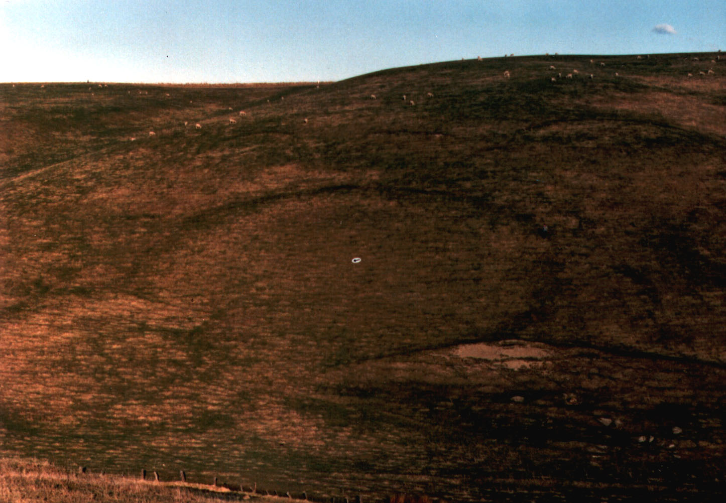
 [1e] Figure M16: A double K8 UFO landing on the slope of mountain near Glendhu Bay, Wanaka. The landing is visible around the centre of this photo. It looks like a digit 3. Each half-circle of this digit 3 is almost 100 meters in diameter. Note that this was a different K8 type UFO vehicle from that shown in Figure M11 above (M11 shows a landing from a single vehicle of K8 type, while this landing is probably left by a cell of flying system of K8 type). [1e] Figure M16: A double K8 UFO landing on the slope of mountain near Glendhu Bay, Wanaka. The landing is visible around the centre of this photo. It looks like a digit 3. Each half-circle of this digit 3 is almost 100 meters in diameter. Note that this was a different K8 type UFO vehicle from that shown in Figure M11 above (M11 shows a landing from a single vehicle of K8 type, while this landing is probably left by a cell of flying system of K8 type).
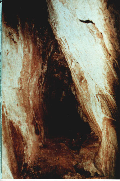 [1e] Figure M17: The tunnel Morona-Santiago in Equador also evaporated by a UFO. [1e] Figure M17: The tunnel Morona-Santiago in Equador also evaporated by a UFO.
 [1e] Figure M18 (a): The Cocklebiddy Cave in Australia evaporated by UFOs. [1e] Figure M18 (a): The Cocklebiddy Cave in Australia evaporated by UFOs.
 [1e] Figure M18 (b): Shape and course of the Cocklebiddy Cave. [1e] Figure M18 (b): Shape and course of the Cocklebiddy Cave.
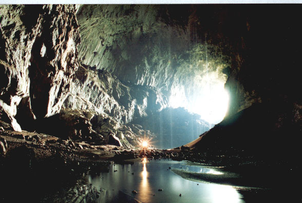 [1e] Figure M18(c): The Deer Cave in Borneor evaporated in rocks by UFOs type K8. [1e] Figure M18(c): The Deer Cave in Borneor evaporated in rocks by UFOs type K8.
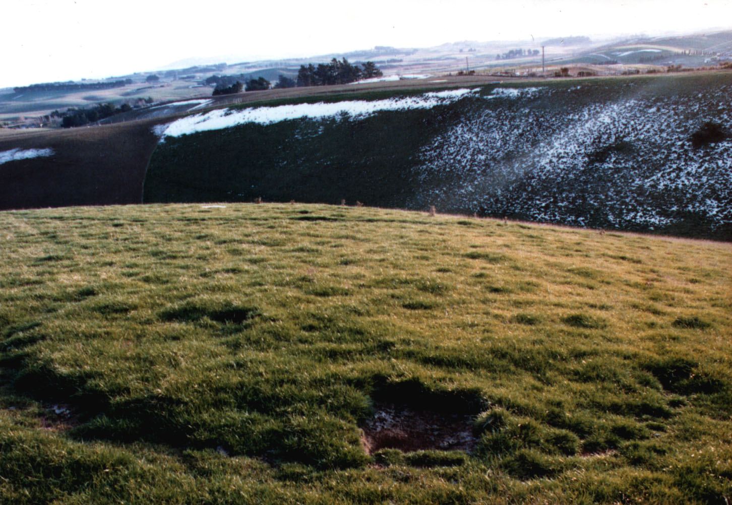
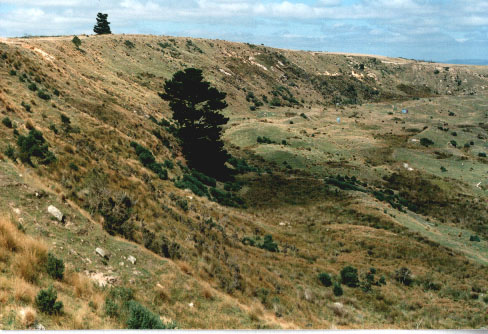
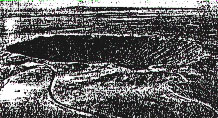
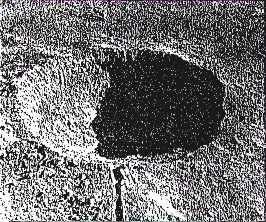
 [1e] Figure M19 (upper): A distant photograph of the Tapanui Crater where a UFO exploded in 1178 AD. Note that this crater is around 1 km in diameter, while the tree visible at the top is a fully grown pine.
More interesting curiosities of New Zealand, includin the above crater formed in the result of a UFO explosion near Tapanui, is provided on a separate web page, which in "Menu 2" and "Menu 4" is named
New Zealand. [1e] Figure M19 (upper): A distant photograph of the Tapanui Crater where a UFO exploded in 1178 AD. Note that this crater is around 1 km in diameter, while the tree visible at the top is a fully grown pine.
More interesting curiosities of New Zealand, includin the above crater formed in the result of a UFO explosion near Tapanui, is provided on a separate web page, which in "Menu 2" and "Menu 4" is named
New Zealand.
 [1e] Figure M19(low): An eastern section of the Tapanui Crater where UFOs exploded in 1178 AD.
More details about the UFO explosion near Tapanui is provided on a separate web page, which in "Menu 2" and "Menu 4" is named
Tapanui. [1e] Figure M19(low): An eastern section of the Tapanui Crater where UFOs exploded in 1178 AD.
More details about the UFO explosion near Tapanui is provided on a separate web page, which in "Menu 2" and "Menu 4" is named
Tapanui.
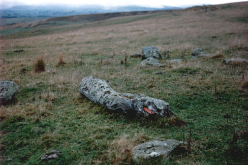 [1e] Figure M20 (a): Remains of trees fallen down during the Tapanui explosion. Totara around 200 metres from the Tapanui Crater. [1e] Figure M20 (a): Remains of trees fallen down during the Tapanui explosion. Totara around 200 metres from the Tapanui Crater.
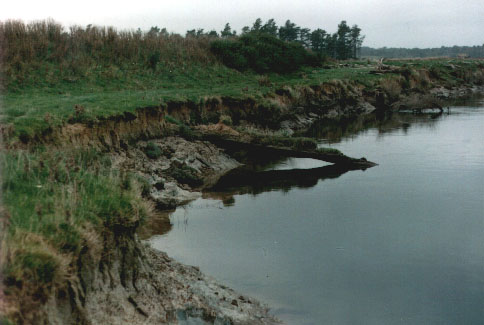 [1e] Figure M20 (b): Unearthed ancient trees at the outlet from Mataura river. [1e] Figure M20 (b): Unearthed ancient trees at the outlet from Mataura river.
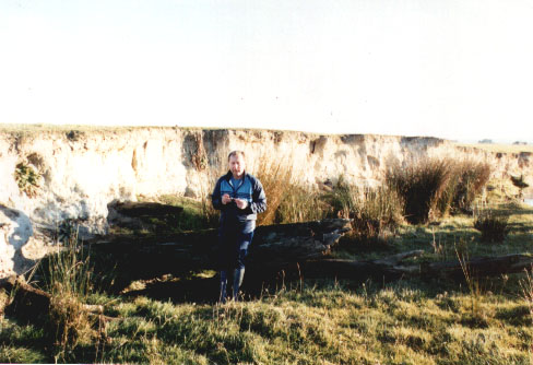 [1e] Figure M20 (c): Myself (Dr Jan Pajak) by a totara tree at Black Gully Creek. [1e] Figure M20 (c): Myself (Dr Jan Pajak) by a totara tree at Black Gully Creek.
 [1e] Figure M20 (d): Trees sticking out from Black Gully Creek. [1e] Figure M20 (d): Trees sticking out from Black Gully Creek.
 [1e] Figure M21: Damage caused by the Tapanuii explosion in the South Island of New Zealand. [1e] Figure M21: Damage caused by the Tapanuii explosion in the South Island of New Zealand.
 [1e] Figure M22 (high): The inner topography of the Tapanui Crater. (Overhead sketch.) [1e] Figure M22 (high): The inner topography of the Tapanui Crater. (Overhead sketch.)
 [1e] Figure M22 (low): Vertical cross section of the crater's topography. [1e] Figure M22 (low): Vertical cross section of the crater's topography.
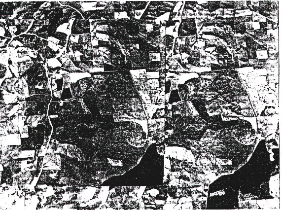 [1e] Figure M23: Two aerial photographs of the Tapanui Crater. They allow a stereoscopic (3D) view of the area - if one uses stereoscopic glasses. (Notice two elliptical images oif the crater, located around Z=40% from the bottom, and X=50% plus X=90% from the left of screen.) [1e] Figure M23: Two aerial photographs of the Tapanui Crater. They allow a stereoscopic (3D) view of the area - if one uses stereoscopic glasses. (Notice two elliptical images oif the crater, located around Z=40% from the bottom, and X=50% plus X=90% from the left of screen.)
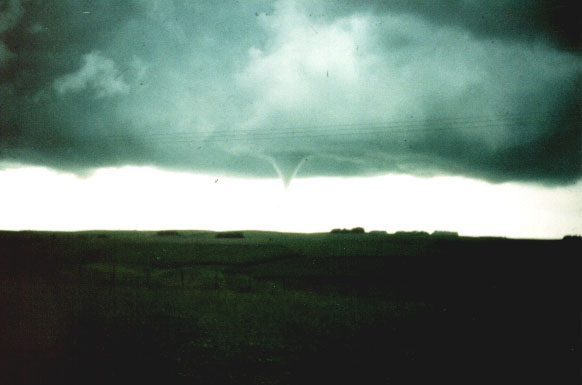 [1e] Figure M24 (high): Photographs of a tornado by Mrs Diane Chittock. This tornado develops the funnel right above the Tapanui Crater.
More details about attributes and mechanism of tornados induced technologically by UFO vehicles is provided on a separate web page, which in "Menu 2" and "Menu 4" is named
Tornado. [1e] Figure M24 (high): Photographs of a tornado by Mrs Diane Chittock. This tornado develops the funnel right above the Tapanui Crater.
More details about attributes and mechanism of tornados induced technologically by UFO vehicles is provided on a separate web page, which in "Menu 2" and "Menu 4" is named
Tornado.
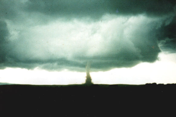 [1e] Figure M24 (low): Photographs of a fully developed tornado by Mrs Diane Chittock. Fully developed tornado drifts away from the crater.
More details about tornados and hurricanes induced technologically by UFO vehicles is provided on a separate web page, which in "Menu 2" and "Menu 4" is named
Tornado. [1e] Figure M24 (low): Photographs of a fully developed tornado by Mrs Diane Chittock. Fully developed tornado drifts away from the crater.
More details about tornados and hurricanes induced technologically by UFO vehicles is provided on a separate web page, which in "Menu 2" and "Menu 4" is named
Tornado.
 [1e] Figure M25: A magnetised metallic piece from Tapanui Crater. Research shown that it contains iron and grains of pure aluminium, mixed with sand and melted. But aluminium does not appear in a pure form in nature! [1e] Figure M25: A magnetised metallic piece from Tapanui Crater. Research shown that it contains iron and grains of pure aluminium, mixed with sand and melted. But aluminium does not appear in a pure form in nature!
 [1e] Figure M26 (upper): A china stone that formad a small crater by Black Gully Creek. [1e] Figure M26 (upper): A china stone that formad a small crater by Black Gully Creek.
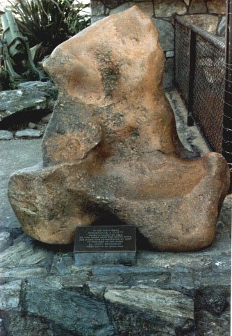 [1e] Figure M26 (lower): Famous China stone from Roxburgh square. A is famous because when it was found a whole pocket of gold was covering its surface. [1e] Figure M26 (lower): Famous China stone from Roxburgh square. A is famous because when it was found a whole pocket of gold was covering its surface.
 [1e] Figure M27 (upper): The Siberian Taiga after the Tunguska explosion. From recent research. [1e] Figure M27 (upper): The Siberian Taiga after the Tunguska explosion. From recent research.
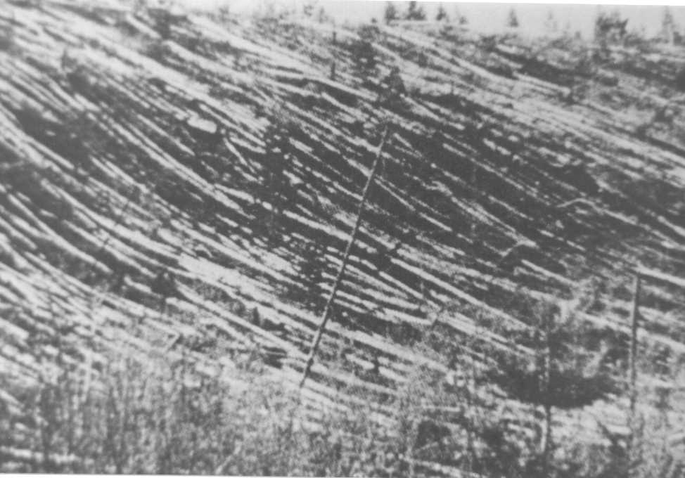 [1e] Figure M27 (lower): Tunguska Taiga fallen down by a UFO explosion in 1908. A frame from the original old Russian film.
It is worth to know, that the UFO explison of 1908 in Tunguska, Central Siberia, is elaborated in much more details in the monograph [5e], copies of which can be downloaded free of charge via web pages, which in "Menu 2" and "Menu 4" are marked
Text of [5e]. [1e] Figure M27 (lower): Tunguska Taiga fallen down by a UFO explosion in 1908. A frame from the original old Russian film.
It is worth to know, that the UFO explison of 1908 in Tunguska, Central Siberia, is elaborated in much more details in the monograph [5e], copies of which can be downloaded free of charge via web pages, which in "Menu 2" and "Menu 4" are marked
Text of [5e].
 [1e] Figure M28 (a): Parabolic-bowl craters from uderground explosions. Diabolo Crater in Arisona, USA, side view. [1e] Figure M28 (a): Parabolic-bowl craters from uderground explosions. Diabolo Crater in Arisona, USA, side view.
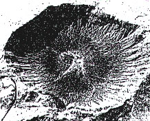 [1e] Figure M28 (b): Diabolo Crater in Arisona, top view. [1e] Figure M28 (b): Diabolo Crater in Arisona, top view.
 [1e] Figure M28 (c): Axial cross-section of Diabolo Crater. [1e] Figure M28 (c): Axial cross-section of Diabolo Crater.
 [1e] Figure M28 (d): Schooner Crater, USA, formed by a nuclear explosion. [1e] Figure M28 (d): Schooner Crater, USA, formed by a nuclear explosion.
 [1e] Figure M28 (e): Vertical cross-section of the Schooner Crater. [1e] Figure M28 (e): Vertical cross-section of the Schooner Crater.
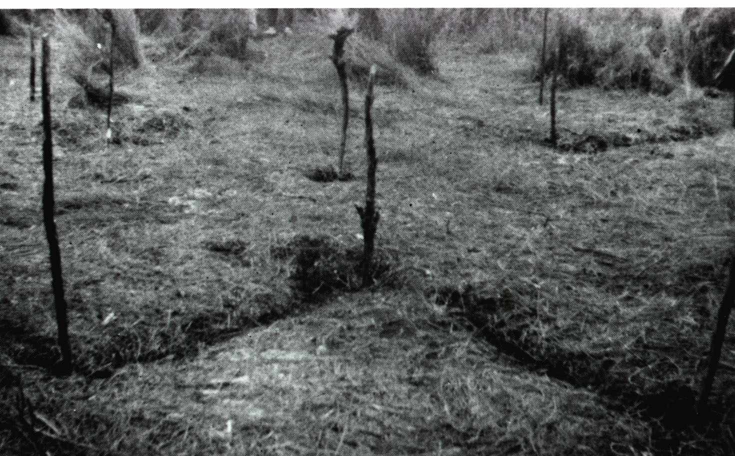
 [1e] Figure M29 (a): The "Telegraphic Pole" forest left in the ground zero at the site of UFO explosion in Tunguska. [1e] Figure M29 (a): The "Telegraphic Pole" forest left in the ground zero at the site of UFO explosion in Tunguska.
 [1e] Figure M29 (b): The upright trees still standing in Hiroshima Castle. [1e] Figure M29 (b): The upright trees still standing in Hiroshima Castle.
 [1e] Figure M30: Similarities between UFO explosion sites in Tapanui, New Zealand, and in Tunguska, Siberia. [1e] Figure M30: Similarities between UFO explosion sites in Tapanui, New Zealand, and in Tunguska, Siberia.
Chapter N:
 [1e] Figure N1: UFOnauts and their vehicle drawn by S. Maslowski (9 years old). [1e] Figure N1: UFOnauts and their vehicle drawn by S. Maslowski (9 years old).
Notice that because of the large size of this illustration, at Web sites "*.50megs.com" it is shown at the cost of its quality. Therefore, in a full quality this illustration can be seen on Web sites at "*.20m.com" servers, e.g. at ufonauts.20m.com.
 [1e] Figure N1 (framed): A drawing of Magnocraft type K3 in the same position as that UFO. [1e] Figure N1 (framed): A drawing of Magnocraft type K3 in the same position as that UFO.
 [1e] Figure N2: A UFOnaut with a glowing belt. [1e] Figure N2: A UFOnaut with a glowing belt.
 [1e] Figure N3: One flash picture of a UFOnaut by Jeff Greenhaw. [1e] Figure N3: One flash picture of a UFOnaut by Jeff Greenhaw.
 [1e] Figure N4: A UFOnaut calling himself "Ausso". [1e] Figure N4: A UFOnaut calling himself "Ausso".
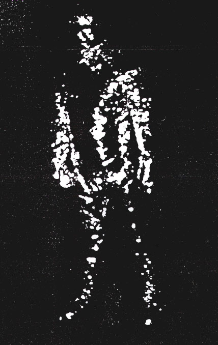
 [1e] Figure N5: A UFOnaut climbing a wall like an insect (it means that a magnetic propulsion was used). [1e] Figure N5: A UFOnaut climbing a wall like an insect (it means that a magnetic propulsion was used).
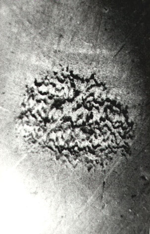 [1e] Figure N6: One of several footprint of an UFOnaut left on PVC floor. [1e] Figure N6: One of several footprint of an UFOnaut left on PVC floor.
Chapter O:
 [1e] Figure O1: A four-propulsor UFO which abducted the late Jan Wolski. [1e] Figure O1: A four-propulsor UFO which abducted the late Jan Wolski.
 [1e] Figure O2 (a): A night apearence of a four-propulsor UFO. (a) Witnesse's original sketch of this UFO. [1e] Figure O2 (a): A night apearence of a four-propulsor UFO. (a) Witnesse's original sketch of this UFO.
 [1e] Figure O2 (b): My (Dr Jan Pajak) reconstruction of this UFO. [1e] Figure O2 (b): My (Dr Jan Pajak) reconstruction of this UFO.
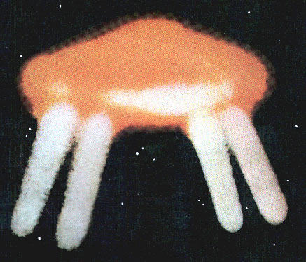 [1e] Figure O3: A photograph of four-propulsor UFO. [1e] Figure O3: A photograph of four-propulsor UFO.
Chapter P:
 [1e] Figure P1: A reduced model of K3 type Magnocraft. [1e] Figure P1: A reduced model of K3 type Magnocraft.
 [1e] Figure P2: A geometrical model of K6 type Magnocraft. [1e] Figure P2: A geometrical model of K6 type Magnocraft.
 Dr Jan Pajak: Photograph of the author of this monograph [1e] "Advanced Magnetic Propulsion Systems", taken in Akaroa, New Zealand in 1983 (i.e. in at the time when this monograph [1e] started to eventuate). Dr Jan Pajak: Photograph of the author of this monograph [1e] "Advanced Magnetic Propulsion Systems", taken in Akaroa, New Zealand in 1983 (i.e. in at the time when this monograph [1e] started to eventuate).
Notice: Illustrations for the remaining chapters of this monograph
are displayed on different web pages, links to which are provided below in "Part #D".
Part #D: Links to web pages which display subsequent sets of illustrations for [1e]:
Because illustrations require a lot of computer memory,
and thus they download rather slowly and make the web page hard to scroll, there is
a practical limit to how many illustrations can be shown on a single web page. For
this reasons, all illustrations for [1e] are split into 4 separate web pages. This is just
one of these. Here are links to remaining web pages with these illustrations:
Links to illustrations of [1e] and to related texts:
Labels: The label "E" marks the web page with text and illustrations for the English-language version of this monograph.
Labels "1st, 2nd, 3rd Figures" mark the web pages with illustrations for subsequent volumes and chapters.
The label "T" marks the web page with the text of English-language version of this monograph
which is designed so as to load much faster because it does NOT show graphics at the loading
stage but only after the user clicks on subsequent Figures to display them.
The label "P" marks the web page with text of a Polish-language equivalent of this monograph.
Part #E:
Web pages which present various aspects of devices elaborated in monograph [1e]:
Various aspects of the Magnocraft, Oscillatory
Chamber, and UFOs, described in monograph
[1e] disseminated free of charge via this web page,
are also summarised on a number of other totaliztic
web pages. Let us list here the most interesting
out of these:
magnocraft.htm - explains the design of a starship which utilises Oscillatory Chambers for interstellar flights.
oscillatory_chamber.htm - summarises design, operation and applications of Oscillatory Chambers.
propulsion.htm - reveals applications of Oscillatory Chambers for purposes of transportation.
eco_cars.htm - describes, amongst others, declarations regarding Oscillatory Chambers for storing energy.
telekinetics.htm - describes phenomenon for generation of "free energy".
free_energy.htm - describes "free energy" devices that were build already.
immortality.htm - explain how Oscillatory Chambers provide people with a real access to immortality.
timevehicle.htm - describes vehicles which travel through time.
hurricane.htm - explains how Magnocrafts propelled by Oscillatory Chambers can control our weather.
tapanui.htm - illustrates what happens when the energy stored in Oscillatory Chambers is accidentally released.
ufo_proof.htm - explains how the physical existence of UFOs was proven formally.
explain.htm - provides examples how to interpret scientifically authentic photographs of UFOs.
tornado.htm - illustrates how UFOs can generate tornadoes technologically.
tapanui.htm - describes the site near Tapanui in New Zealand where a UFO exploded.
day26.htm - explains why the existence and activities of UFOs are "simulated".
petone.htm - explains, amongst others, why the existence and activities of UFOs are "simulated".
quake.htm - documents on the evidence, that the presence of so-called "10 righteous" can stop cataclysms.
seismograph.htm - provides principle of operation of aparatus which remotely detects impending earthquakes.
Part #F:
How with the web page named
"skorowidz_links.htm"
one can find totaliztic descriptions
of topics in which he is interested:
A whole array of topics equally interesting
as these from the above web page, is also
discussed from the angle that is unique to
the philosophy of totalizm. All these related
topics can be found and identified with the use of
content index
prepared especially to make easier finding
these web pages and topics. The name "index"
means a list of "key words" usually provided
at the end of textbooks, which allows to find
fast the description or the topic in which we
are interested. My web pages also has such
a content "index" - only that it is additionally
supplied in green
links
which after "clicking" at them with a mouse
immediately open the web page with the topic
that interest the reader. This content "index"
is provided on the web page named
skorowidz_links.htm.
It can be called from the "organising" part of
"Menu 1" of every totaliztic web page. I would
recommend to look at it and to begin using it
systematically - after all it brings closer hundreds
of totaliztic topics which can be of interest to
everyone.
Part #G:
Emails and contact details to the
author
of this web page:
Current email addresses to the author of
this web page, i.e. officially to
Dr Eng. Jan Pajak
while courteously to Prof. Dr Eng. Jan Pajak,
at which readers can post possible comments,
inquiries, or replies to questions which I ask on
my web pages, are provided on the web page
about me (Dr Eng. Jan Pajak).
That page also provides other commonly used
contact details to the author.
The author's right for the use of courteous
title of "Professor" stems from the custom that
"with professors is like with generals", namely
when someone is
once a professor, than he or she courteously
remains a professor forever. In
turn the author of this web page was a professor
at 4 different universities, i.e. at 3 of them,
from 1 September 1992 untill 31 October 1998,
as an "Associate Professor" from English-based
educational system, while on one university as
a (Full) "Professor" (since 1 March 2007 till
31 December 2007 - means at the last place
of employment in his professional life).
However, please notice that because of my
rather chronic lack of time, I reluctantly
reply to emails which contain JUST time
consuming requests, while simultaneously
they document a complete ignorance of their
author in the topic area which I am researching.
Therefore, if the reader sends a request to me,
I suggest to let me know somehow that he or
she actually went through the trouble of reading
my web pages and learning what these pages
try to say.
Part #H:
Copyrights © 2013 by Dr Jan Pajak:
Copyrights © 2013 by Dr Jan Pajak. All rights
reserved. The author of this web page, i.e.
Dr Eng. Jan Pająk, reserves for himself all
rights to internet web pages, illustrations,
and monographs which he authorises, and
also reserves for himself the intellectual
property of ideas of his authorship which
are presented in these publications.
Have the interesting reading about the technical devices which may completely change our civilisation.
* * *
Date of starting this page: 2001
Date of the most recent update of this web page: 7 January 2013
(Check in "Menu 3" whether there is even a more recent update!)
|