This web page offers the complete text and all
illustrations for the monograph [2e] by Dr Jan Pajak,
"The Oscillatory Chamber, Arkway to the Stars" (1994, ISBN 0-9583380-0-0)
disseminated via this web page free of charge in two languages (English and Polish)
Notices:
(1)
Until the end of June 2009 all monographs and
treatises which I (i.e.
Dr Jan Pająk)
authorise, were translated into a safe and
convenient PDF format (with illustrations
included into their content). They are
offered free of charge for reading by
all interested people. Thus, I recommend
to download these publications for
yourself in such safe format PDF.
After all, in PDF my publications
are "ready to print", and additionally
to the PDF format computer viruses
cannot be attached. Unfortunately,
because of the large size of documents
caused by the inclusion of illustrations
to content of these publications, NOT
every free server with web sites of
totalizm
is able to accommodate these publications.
Therefore, in order to download the
selected publication in the PDF format,
you firstly need to find the server (address)
in the internet under which it is available
free of charge. In order to find it, you need
to check the availability of PDF format in
addresses listed for a given publication
(and web page) in "Menu 3" or in "Menu 4"
from the left margin of this web page.
(2)
In order to download to your computer text of
any of volumes listed below, or in order to
see/download any illustration, just
click
on the underlined
(green)
description chosen from the list below!
(3)
All illustrations from monograph [2e] in the PDF format,
are collected in the last chapter. Therefore, to easier
shift our attention during the reading from the text to
an illustration which is just analysed, it helps to keep
in the computer two copies of this monograph, the
first of which we open on the text that we read directly
from the screen, while the second copy we open on
the illustration which we just are analysing. Then, with
mouse, we just quickly shift (by clicking) from the
window with the text to the window with the illustration
under analysis.
(4)
The device called the "Oscillatory Chamber" which
is described in this monograph [2e], even more
thoroughly is also described in chapters C from
volumes 2 of two other monographs, namely
[1/4] and
[1/5].
Therefore that chapter C from monographs [1/4]
or [1/5] provides a good technical extension for
information contained in this monograph [2].
That device called the "Oscillatory Chamber"
is also described briefly in a number of web
pages (on each web page from a different
point of view), for example on the web page named
oscillatory_chamber.htm -
which is entirely devoted to this device, or in
items #D1 and #D2 of the web page named
propulsion.htm,
in items #H1 to #H3 of the web page named
tapanui.htm,
or in items #D1 to #D5 of the web page named
eco_cars.htm.
A list of web pages describing this device is
provided below in "part #C".
(5)
Illustrations
used in this monograph [2e] are also used in
monographs [1/5], [1/4] and [1e]. Thus, if here
these illustrations come out unclear, they can
also be seen in [1/5], [1/4] or [1e].
Part #A: Free copies of
monograph [2e] in ADOBE.PDF format:
Complete copies of monograph [2e]
"The Oscillatory Chamber, Arkway to the Stars"
(Copyrights © 1994, ISBN 0-9583380-0-0)
in PDF consist of one volume downloadable
free of charge in this part of the page.
Click on the green (underlined) name
below to download one of these copies:
English monograph [2e], format PDF
Polish monograph [2p], format PDF
Part #B: List of content of the English monograph [2e]
"The Oscillatory Chamber, Arkway to the Stars" (Copyrights © 1994, ISBN 0-9583380-0-0).
A. INTRODUCTION
B.THE PERIODIC PRINCIPLE IN THE DEVELOPMENT OF PROPULSION SYSTEMS
B1. Everything in our environment, including the formulation of inventions, is governed by appropriate laws
B2. The basics of propulsion
B2.1. The working medium
B2.2. The primary requirement for building a controllable propulsion system
B3. Application of the Periodic Principle to propulsion systems
B4. The first generation of the magnetic propulsion systems
B4.1. The Magnocraft
B4.1.1. The general design and components of the Magnocraft
B4.1.2. Flight control
B4.1.3. The specifications of the Magnocraft
B4.2. The second motor propulsor pair in the first generation of magnetic propulsion systems
B5. How the "omnibus trend" should culminate in three conventions of the Magnocraft's operation
B6. Three successive generations of magnetic propulsion systems
C.THE TELEKINETIC EFFECT
C1. History of the Telekinetic Effect's discovery
C2. Action of the Telekinetic Effect explained by the Concept of Dipolar Gravity
C3. Experimental confirmation of the Telekinetic Effect
C4. Technological activation of the Telekinetic Effect
C5. Technical utilization of the Telekinetic Effect
C5.1. Utilization of the Telekinetic Effect
for the production of energy
C5.1.1. Review of the main types of
telekinetic power stations built so far
C5.2. Utilization of the Telekinetic Effect
for the transportation purposes
D.THE CONCEPT OF DIPOLAR GRAVITY
D1. Why the Concept of Dipolar Gravity was formulated
D2. The operation of our Universe ruled by dipolar gravity
D2.1. Ether the thinking substance
from the counter world
D2.2. Software models (registers) of material objects
D2.3. Possible gains from the mastery
of the counter world
D3. The interpretation of time
in the Concept of Dipolar gravity
D4. The interpretation of electromagnetic phenomena
in the Concept of Dipolar Gravity
D4.1. What is a magnetic field?
D5. Why, according to the Concept of Dipolar Gravity,
paranormal phenomena must display
electromagnetic character
D6. Telekinesis a power source for free energy devices
and a principle of operation for Teleportation Vehicles
D7. The model of the brain as an input output device
D8. ESP a key to instant benefits from the counter world
D8.1. Perfect Data Base (PDB)
as a theoretical model of ESP
D8.2. How to develop a simplest
pendulum assisted ESP technique
D9. How the Concept of Dipolar Gravity
explains some mysterious phenomena
D10. How the Concept of Dipolar Gravity
merges science with religion
D10.1. The Universe as a whole
possesses its own intellect
D10.2. Moral laws
D10.3. Consistency the measure
of intellectual perfection
D11. An experimental confirmation of the
existence of the counter world
D12. To conclude
E. PHILOSOPHICAL REQUIREMENTS FOR GIVING RECOGNITION TO NEW IDEAS
E1. Everything is possible: we only need
to find out how to achieve it
E2. What is totalizm?
F. THE OSCILLATORY CHAMBER
F1. Why there is a necessity to replace the electromagnet
by the Oscillatory Chamber
F2. The principle of operation of the Oscillatory Chamber
F2.1. The electrical inertia of an inductor as the
motive force for oscillations in a conventional
oscillatory circuit with a spark gap
F2.2. In the modified oscillatory circuit with
a spark gap, the inductance of a stream
of sparks replaces the electrical inertia
of an inductor
F2.3. The combining of two modified circuits forms an
"Oscillatory Chamber" producing a
bipolar magnetic field
F3. The future appearance of the Oscillatory Chamber
F3.1. Three generations of the Oscillatory Chambers
F4. Mathematical model of the Oscillatory Chamber
F4.1. Resistance of the Oscillatory Chamber
F4.2. Inductance of the Oscillatory Chamber
F4.3. Capacitance of the Oscillatory Chamber
F4.4. The "sparks' motivity factor"
and its interpretation
F4.5. Condition for the oscillatory response
F4.6. The period of pulsation of the chamber's field
F5. How the Oscillatory Chamber eliminates
the drawbacks of electromagnets
F5.1. Mutual neutralization of the two
opposite electro magnetic forces
F5.2. Independence of the magnetic field production from
the continuity and efficiency of the energy supply
F5.3. Elimination of energy loss
F5.3.1. Premises for the recovery of
all heat dissipated by sparks
F5.4. Releasing the structure of the chamber from
the destructive action of electric potentials
F5.5. Amplifying control of the period of field pulsation
F6. Advantages of the Oscillatory Chamber over electromagnets
F6.1. Formation of the "twin chamber capsule"
able to control the output
without altering the energy involved
F6.2. Formation of the "spider configuration"
F6.3. The non attraction of ferromagnetic objects
F6.4. Multidimensional transformation of energy
F6.5. Continuous oscillating a unique electromagnetic
phenomenon allowing the Oscillatory Chamber
to absorb unlimited amounts of energy
F6.6. Function as an enormously
capacious accumulator of energy
F6.7. Simplicity of production
F7. Advancements in the practical completion of the
Oscillatory Chamber
F7.1. Experimental devices
F7.2. Stages, goals, and ways of their achieving
in the experimental building
of the Oscillatory Chamber
F7.3. An invitation to take part in the development
of the Oscillatory Chamber
F7.4. The author's policy of the public ownership
of the Oscillatory Chamber principles
F8. Future applications of the Oscillatory Chamber
F9. Monographs describing the Oscillatory Chamber
F10. Symbols, notation, and units used in this chapter
G. THE (DISCOIDAL) MAGNOCRAFT
G1. The magnetic propulsor
G1.1. The principle of tilting the magnetic axis
in a Magnocraft's propulsor
G1.2. The propulsion unit
G1.3. Using propulsors as searchlights
G2. The shell of the Magnocraft
G2.1. Terminology describing various parts
of the Magnocraft's shell
G2.2. The Magnocraft's compartments
G2.3. The Magnocraft's facilities
G2.4. Materials for the Magnocraft's shell
G2.4.1. The electrodynamic model
of magnetoreflectiveness
G3. Shapes of the coupled Magnocraft
G3.1. The six classes of the Magnocraft arrangements
G3.1.1. Flying complexes
G3.1.2. Semi attached configurations
G3.1.3. Detached configurations
G3.1.4. Carrier platforms
G3.1.5. Flying systems
G3.1.6. Flying clusters
G3.2. The principles of coupling and decoupling
G3.3. The hydraulic substance filling the space
between the craft ("angel's hair")
G3.4. The black bars of the magnetic field
G4. The conditions defining the
shape of the Magnocraft's shell
G4.1. The condition of equilibrium between
the thrust and stabilization forces
G4.2. The condition that the number of side propulsors
to be a multiple of four
G4.3. The basic condition for the
force stability of the structure
of a craft which uses magnetic propulsors
G4.4. The condition for expressing the "K" factor
by the ratio of outer dimensions
G4.5. The condition for optimum coupling
into flying systems
G4.6. The condition under which the flanges coincide
G4.7. Types of Magnocraft
G4.8. Identifying the types of Magnocraft
G4.9. The magnetic framework
G5. The magnetic field of the Magnocraft
G5.1. The starting flux
G5.2. The naming of the magnetic poles
G5.3. The effective length of the Oscillatory Chamber
and the net magnetic force
G5.4. The determination of the value
for the "starting flux"
G5.5. The energy of the Magnocraft's field
G5.6. The energy of the Magnocraft's field
is self rechargeable
G5.7. Why the Earth's magnetic field
should not be called "weak"
G5.8. The Earth's magnetic field
is able to carry out technically useful work
G6. The manoeuvring of the Magnocraft
G6.1. Ascent, hovering, and descent
G6.2. Meridional flights
G6.3. Latitudinal flights
G6.3.1. An experiment showing the existence
of the latitudinal thrust force
G6.3.2. The deduction that explains
the principles of the latitudinal
thrust force formation
G6.3.3. How to determine the direction
of the thrust force
created by the magnetic whirl
(the "rolling sphere rule")
G6.4. The rotation of the Magnocraft
G7. The magnetic whirl
G7.1. The magnetic circuits in the Magnocraft
G7.2. Creation of a magnetic whirl
G7.3. The ionic picture of a whirl
G8. Three modes of the Magnocraft's operation
G8.1. Visual recognition of the mode
G8.2. The SUB system for indicating the Magnocraft's
mode of operation
G9. The properties of the Magnocraft
G9.1. The properties of the Magnocraft during the
magnetic whirl mode of operation
G9.1.1. Properties of the tunnels made in rocks
by the Magnocraft
G9.2. The properties of the Magnocraft during the
throbbing mode of operation
G9.3. Humming noises appearing in both the magnetic
whirl and throbbing modes of operation
G9.4. The properties of the Magnocraft
during the magnetic lens mode of operation
G9.4.1. The magnetic lens action
in ascending Magnocraft
G10. Landing sites of the Magnocraft
G10.1. Environmental damage
caused by the landed Magnocraft
G10.2. Three main cases of the Magnocraft's landings
G10.3. The landing sites for the magnetic circuits
looped under the ground
G10.3.1. Determination of the
Magnocraft's dimensions
from the scorch marks
left at landing sites
G10.4. The landing sites with magnetic circuits
looped along the surface of the ground
G10.5. The landing sites for circuits looped in the air
G10.6. The landing sites formed by
arrangements of the Magnocraft
G11. Explosion sites of the Magnocraft
G12. Summary of the attributes of the Magnocraft
G13. Military aspects of the Magnocraft
G13.1. Use of the Magnocraft as
a weapons platform
or transportation facility
G13.2. Use of the Magnocraft
as a selectively acting weapon
H. THE FOUR PROPULSOR SPACECRAFT
H1. The general design of the Four Propulsor Spacecraft
H2. The operation of the Four Propulsor Spacecraft
H3. The properties of the Four Propulsor Spacecraft
H4. The external appearance of the Four-Propulsor Spacecraft
H5. Identification of the type of Four Propulsor Spacecraft
I. MAGNETIC PERSONAL PROPULSION
I1. The standard garment of personal propulsion
I2. Principles of operation of magnetic personal propulsion
I3. The garment with main propulsors in epaulettes
I4. A special version of personal propulsion
with cushions around the hips
I5. Capabilities of personal propulsion
I6. Summary of the attributes of personal propulsion
J. MAGNOCRAFT OF THE SECOND AND THIRD GENERATIONS
J1. Teleportation Vehicle as the Magnocraft of
the second generation
J2. The Magnocraft of the third generation
(called also "Time Vehicles")
J3. Three generations of the Magnocraft
and their identification
K. EVIDENCE THAT MAGNOCRAFT-LIKE UFOs ALREADY OPERATE ON EARTH
K1. Summary of the formal proof that
"UFOs are Magnocraft which are already operational"
K2. Permanent evidence for the continuous UFO activity on Earth
K2.1. UFO explosion sites
K2.2. Long, straight tunnels evaporated
during underground flights of UFOs
K2.3. UFO landing sites
K2.4. Fragments of UFO shells
K2.5. Other material evidence for UFO activity
K3. Chapter K reference material
L. EVIDENCE CONFIRMING THE USE OF THE OSCILLATORY CHAMBER ON UFOs
L1. Contemporary observations and photographs of
Oscillatory Chambers used in UFO propulsors
L1.1. Columns of magnetic field yield from UFO propulsors
are square in the cross section
L1.2. Outlets of UFO propulsors are square and reveal gold
or yellow bands of electric sparks rotating inside
L1.3. Twin chamber capsules formed from two Oscillatory
Chambers are frequently observed in UFOs
and even photographed
L1.4. Oscillatory Chambers have been seen on the decks
of UFOs as described by numerous abductees
L2. Indirect confirmations that UFOs
use Oscillatory Chambers
L3. Material (hard) evidence left by UFO Oscillatory Chambers
L4. Mythological descriptions of the Oscillatory Chamber
L5. Historical descriptions of the Oscillatory Chamber
L6. To conclude this chapter
M. CONTEMPORARY SIGHTINGS OF FOUR PROPULSOR UFOs
M1. Classic sightings of four propulsor UFOs
M2. Photographs of four propulsor UFOs
M3. Concluding this chapter
N. SIGHTINGS OF UFONAUTS WHO USE MAGNETIC PERSONAL PROPULSION
N1. The characteristic appearance of the
wearers of personal propulsion
N2. The extraordinary abilities of UFOnauts
wearing personal propulsion garments
N3. Scorched footprints left by personal propulsion
of a UFOnaut
N4. Mythological descriptions of the use of
magnetic personal propulsion
N5. The consequences of the observation of
personal propulsion of UFOnauts
O. SIGHTINGS OF UFOs OF THE SECOND AND THIRD GENERATIONS
O1. Observations of Teleportation Vehicles in operation
O2. The evidence confirming the existence of Time Vehicles
P. UFO ABDUCTEES
P1. How to identify UFO abductees
P2. How to confirm objectively
that someone is repetitively taken onto the deck of a UFO
P3. Some implications of UFO abductions
P4. Research of UFO abductees
P4.1. Research which could be completed by
UFO abductees themselves
P4.2. Examples of research topics for
students and scientists
P5. To conclude
Q. SUMMARY
R. LITERATURE COMPLEMENTING THIS MONOGRAPH
S. ABOUT THE AUTHOR
Tables (B1, C1, F1, G1, G2, G3, and H1) and 104 Illustrations (B1 to O1)
Z. APPENDIXes (e.g. Abduction of Miss Nosbocaj onto the deck of a UFO)
Illustrations:
If the reader downloaded for himself this publication
in the PDF format, then it already contains all illustrations
discussed in its content. However, some photographs
and drawings included into its content, sometimes
needed to be decreased in size, to fit into single
pages of paper of the A4 format. Thus selected
details on photographs and drawings already
included into the PDF format may NOT be visible
clearly enough. For this reason electronic version
of all these photographs and drawings used in
my publications are also made available in the
internet - so that everyone could analyse them
thoroughly in internet, or download to own computer.
This in turn allows to enlarge these illustrations
to any size required - allowing the detailed
analysis and viewing. Furthermore, internet
copies of all illustrations used in this publication
can also be downloaded and included into
copies of this publication disseminated in source
formats such as DOC, WP5, or ZIP (i.e. formats
other than PDF). After all, these other formats
NOT always have illustrations included into them.
* * *
Please notice that NOT all servers (addresses)
contain all illustrations displayed on this web page.
Thus, if under this address any illustration is NOT
shown (i.e. if you can only see the frame of that
illustration), then you need to jump at the same
web page but available under a different address
indicated in "Menu 3" or in "Menu 4", and see this
illustration over there.
Part #C: Illustrations for monograph [2e] (i.e. in English), in formats *.gif or *.jpg.
Notice that you can see the
enlargement
of each illustration from this web site.
For this, it suffices to click on a
(green and underlined link marked "[2e] Figure ?")
which is to open a separate windows with
that illustration. Furthermore, most of the
internet browsers that you may use,
including the popular "Internet Explorer",
allow also to download
each illustration to your own computer,
where it can be looked at, reduced or
enlarged to the size that you may want,
or printed with your own graphical software.
* * *
The Polish version [2p] of this monograph uses slightly different illustrations than the English version [2e].
* * *
Captions for each illustrations are intentionally short on this web page - describing only key points of given illustrations.
The full description of each illustration can be found in captions from the PDF text of monograph [2e].
Chapter G:
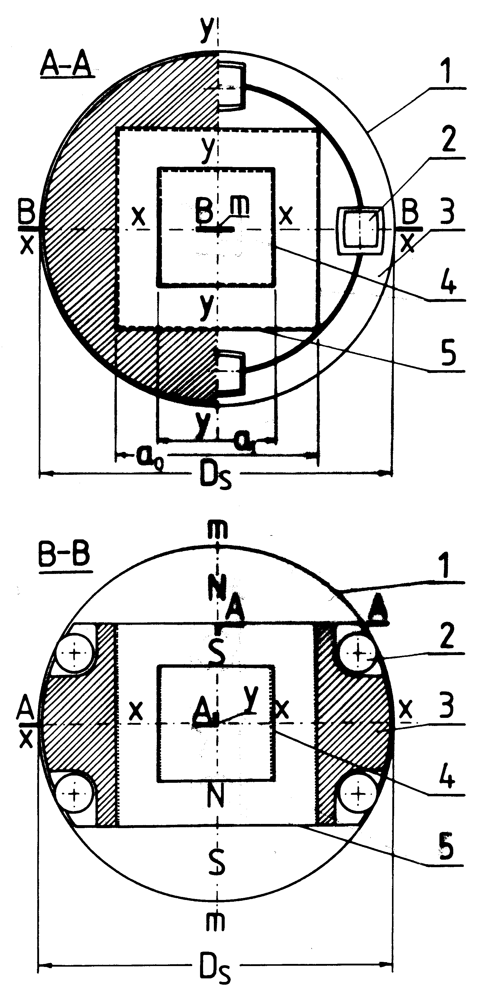 [2e] Figure G1: Principle of tilting the magnetic propulsor. [2e] Figure G1: Principle of tilting the magnetic propulsor.
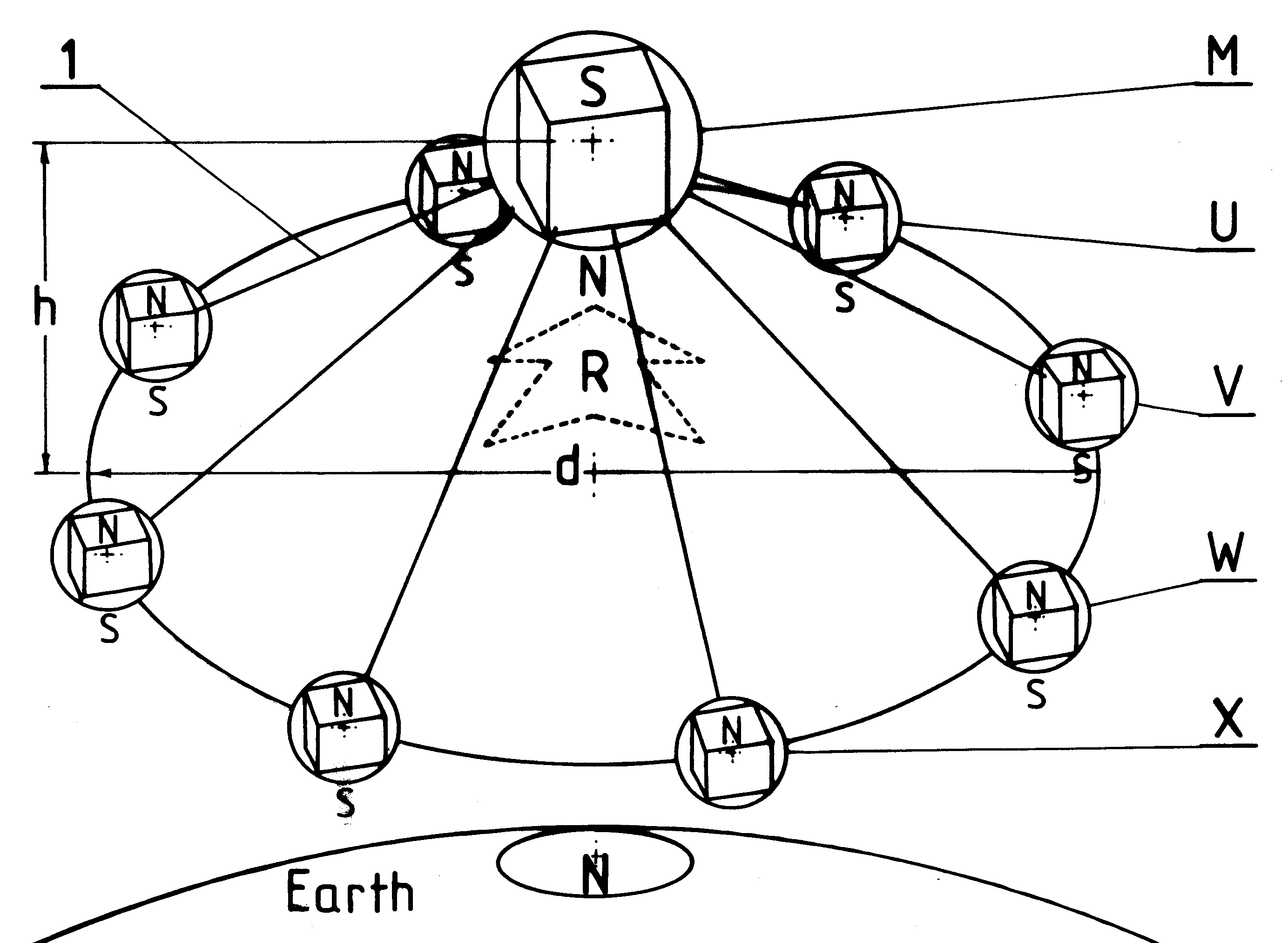 [2e] Figure G2: The magnetic propulsion unit of the Magnocraft. [2e] Figure G2: The magnetic propulsion unit of the Magnocraft.
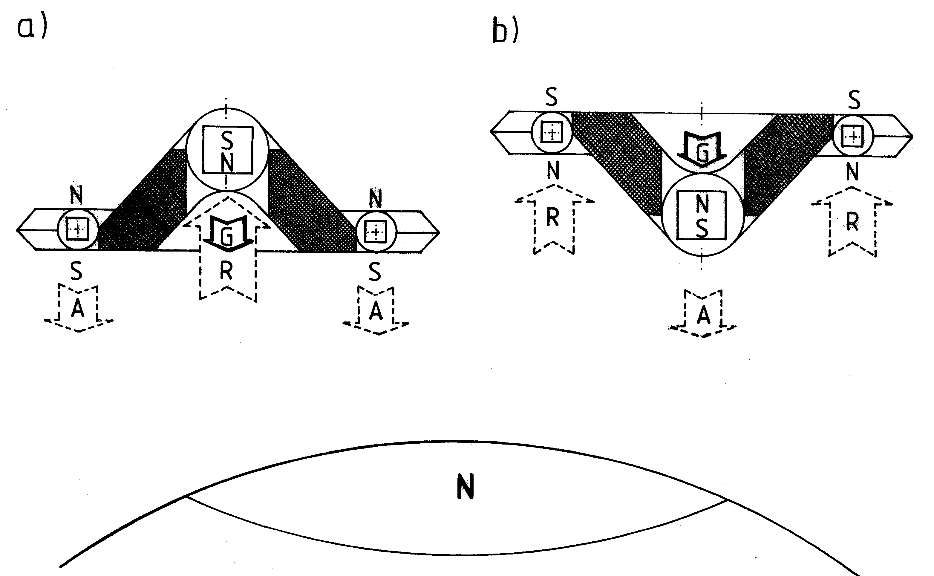 [2e] Figure G3: Two alternative flight postions of the Magnocraft: upright and inverted. [2e] Figure G3: Two alternative flight postions of the Magnocraft: upright and inverted.
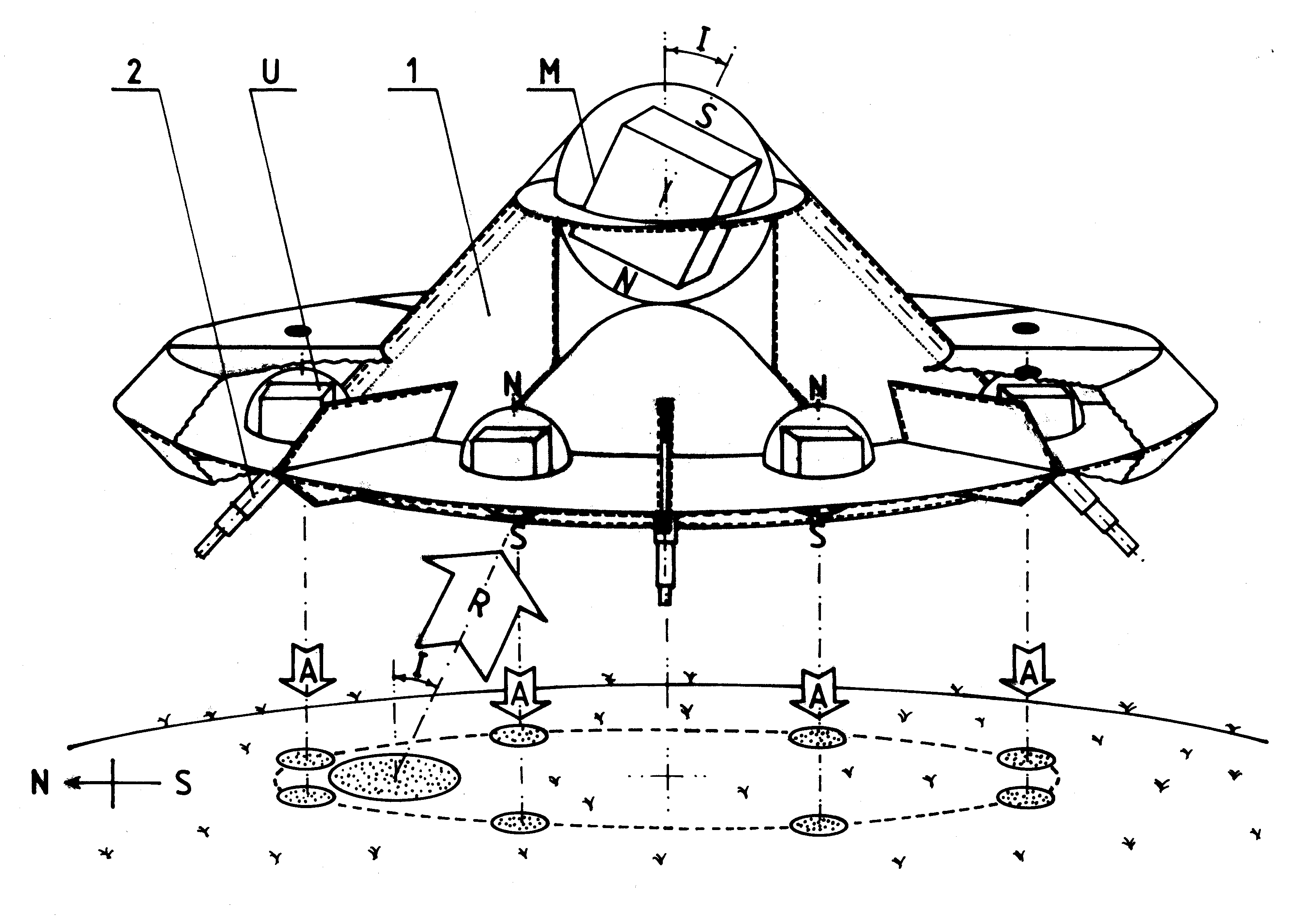 [2e] Figure G4: A side view of the Magnocraft and UFO type K3. [2e] Figure G4: A side view of the Magnocraft and UFO type K3.
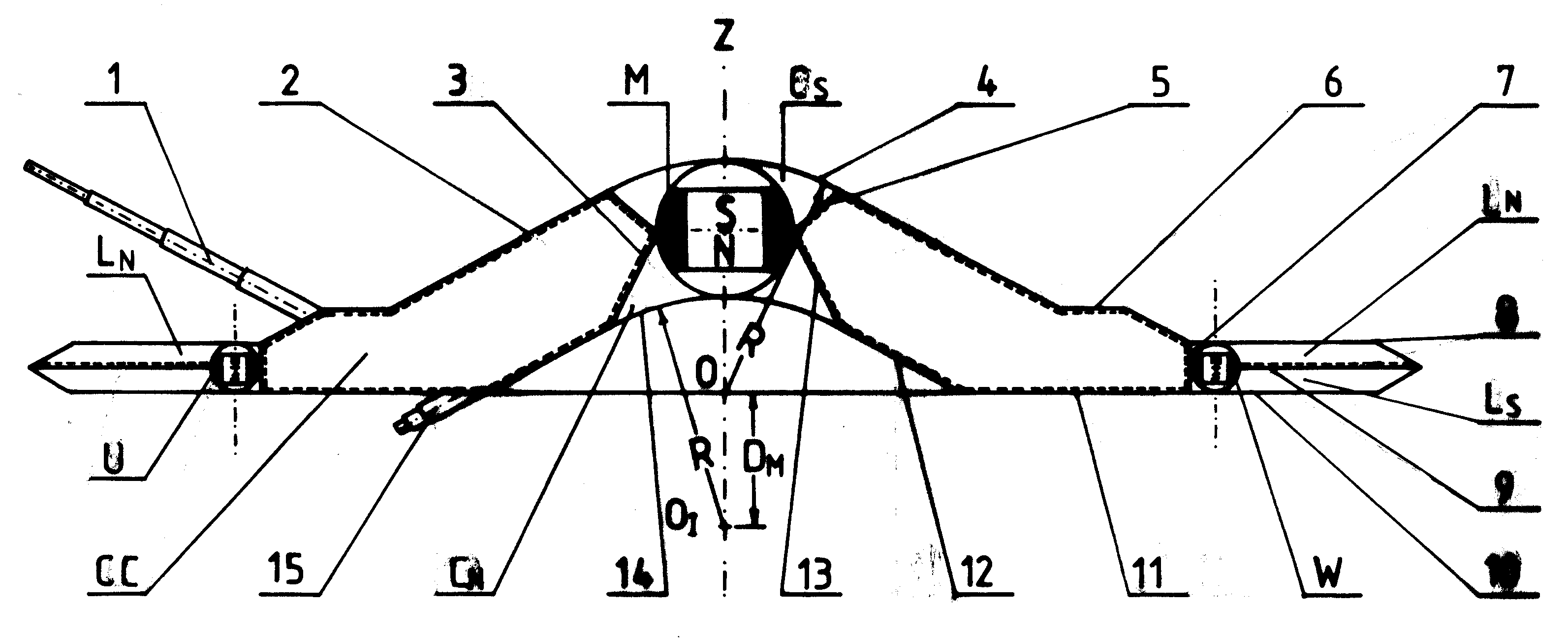 [2e] Figure G5: The Magnocraft type K3 cross-section that shows the design and main features. [2e] Figure G5: The Magnocraft type K3 cross-section that shows the design and main features.
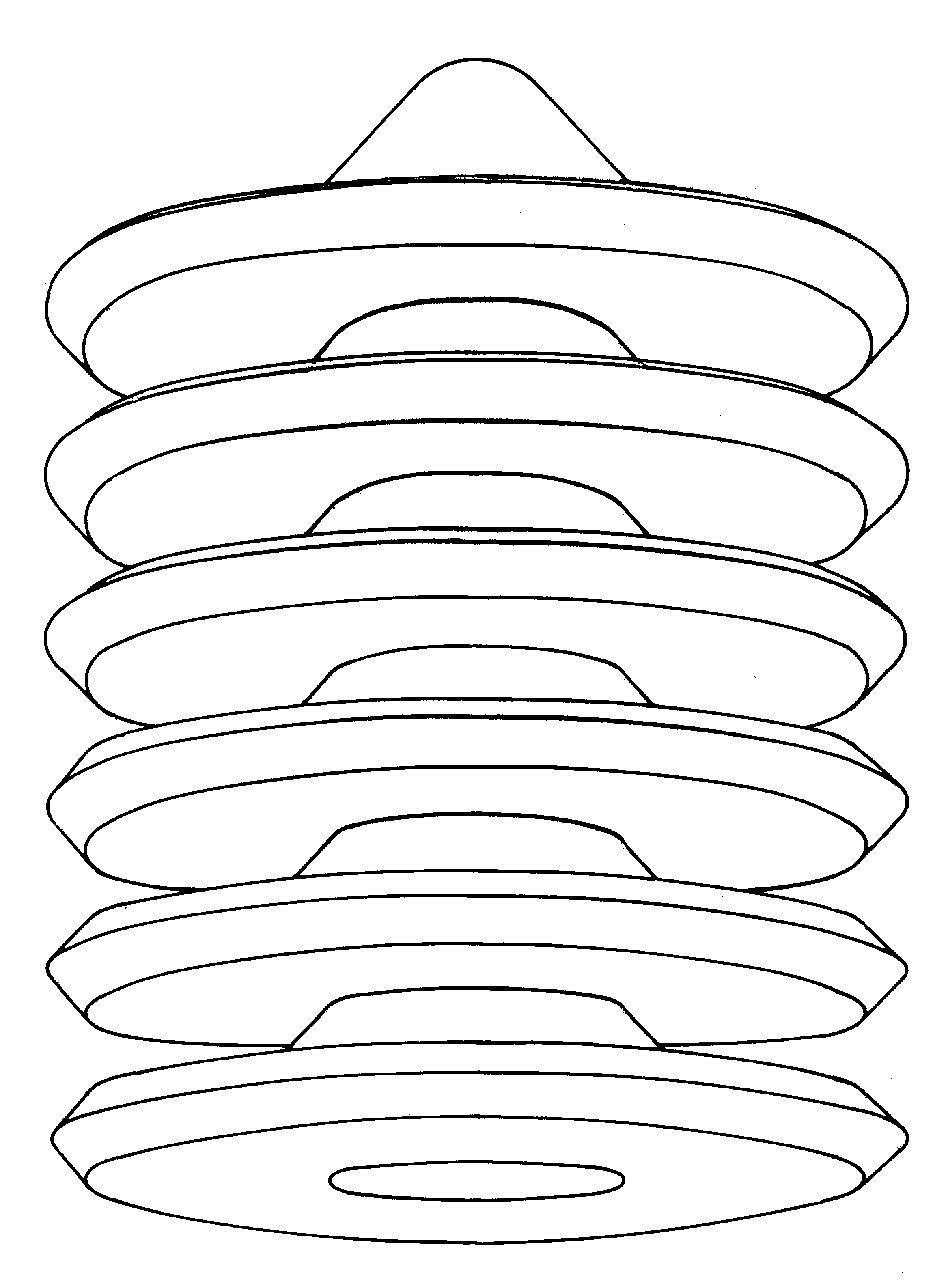 [2e] Figure G6-#1: Flying complexes (cigar shaped)of UFOs and Magnocraft. [2e] Figure G6-#1: Flying complexes (cigar shaped)of UFOs and Magnocraft.
 [2e] Figure G6-#2: Semi-attached configuration. [2e] Figure G6-#2: Semi-attached configuration.
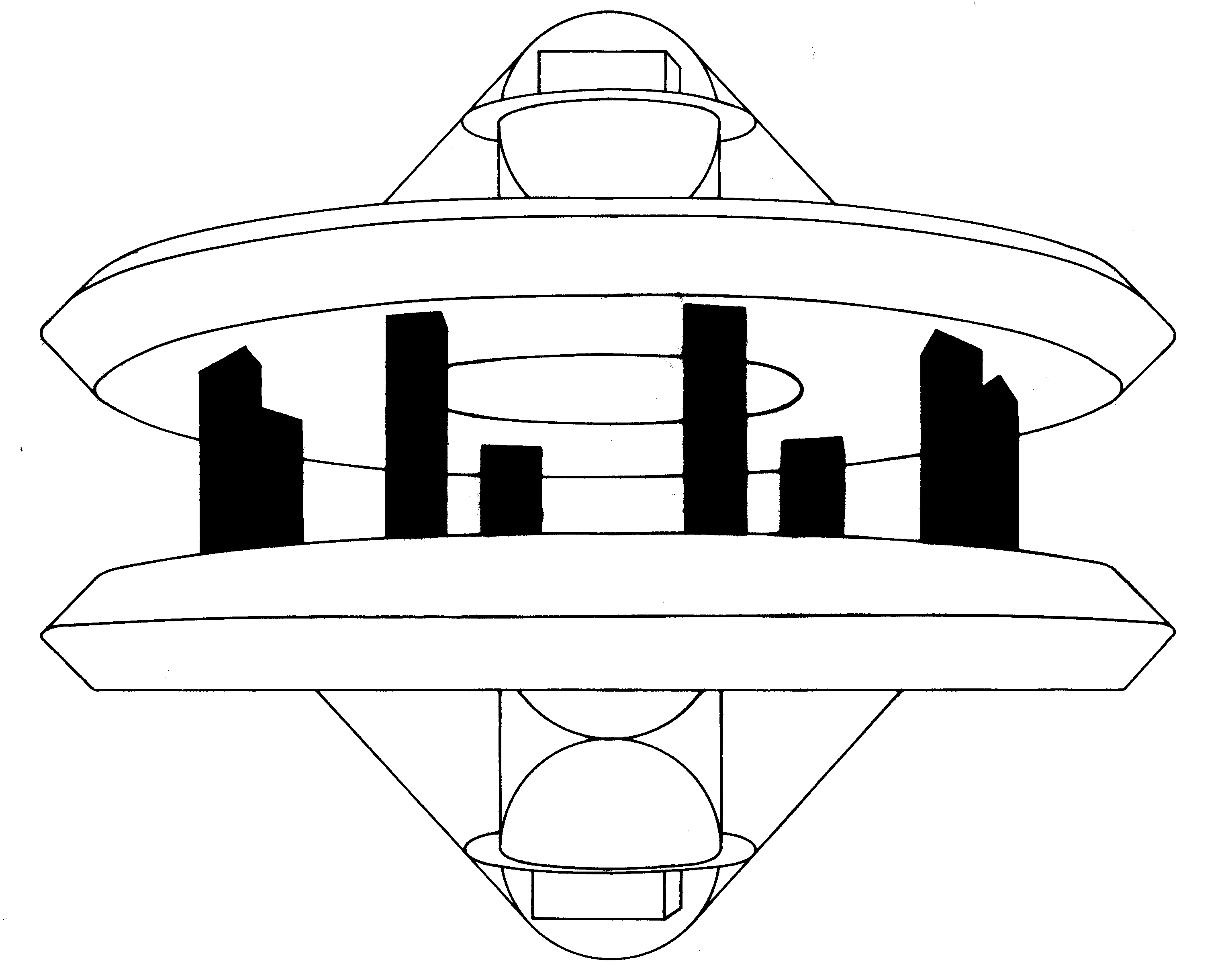 [2e] Figure G6-#3: Detached configuration. [2e] Figure G6-#3: Detached configuration.
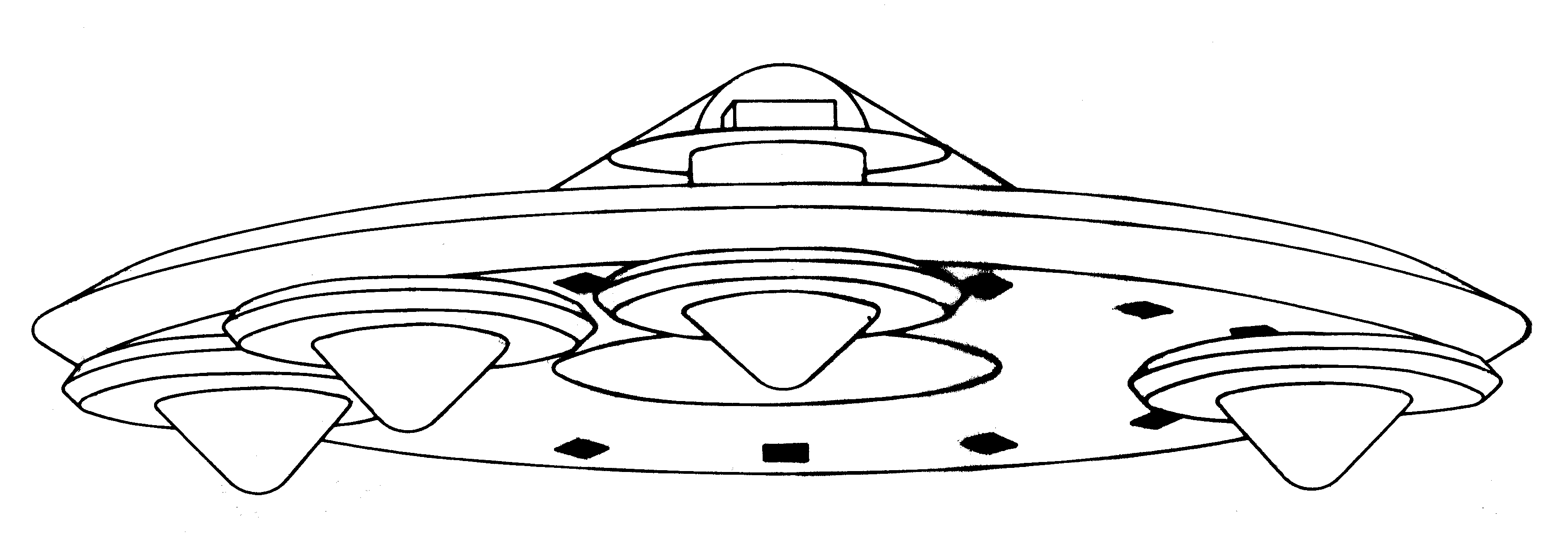 [2e] Figure G6-#4: A carrier platform (a mother ship). [2e] Figure G6-#4: A carrier platform (a mother ship).
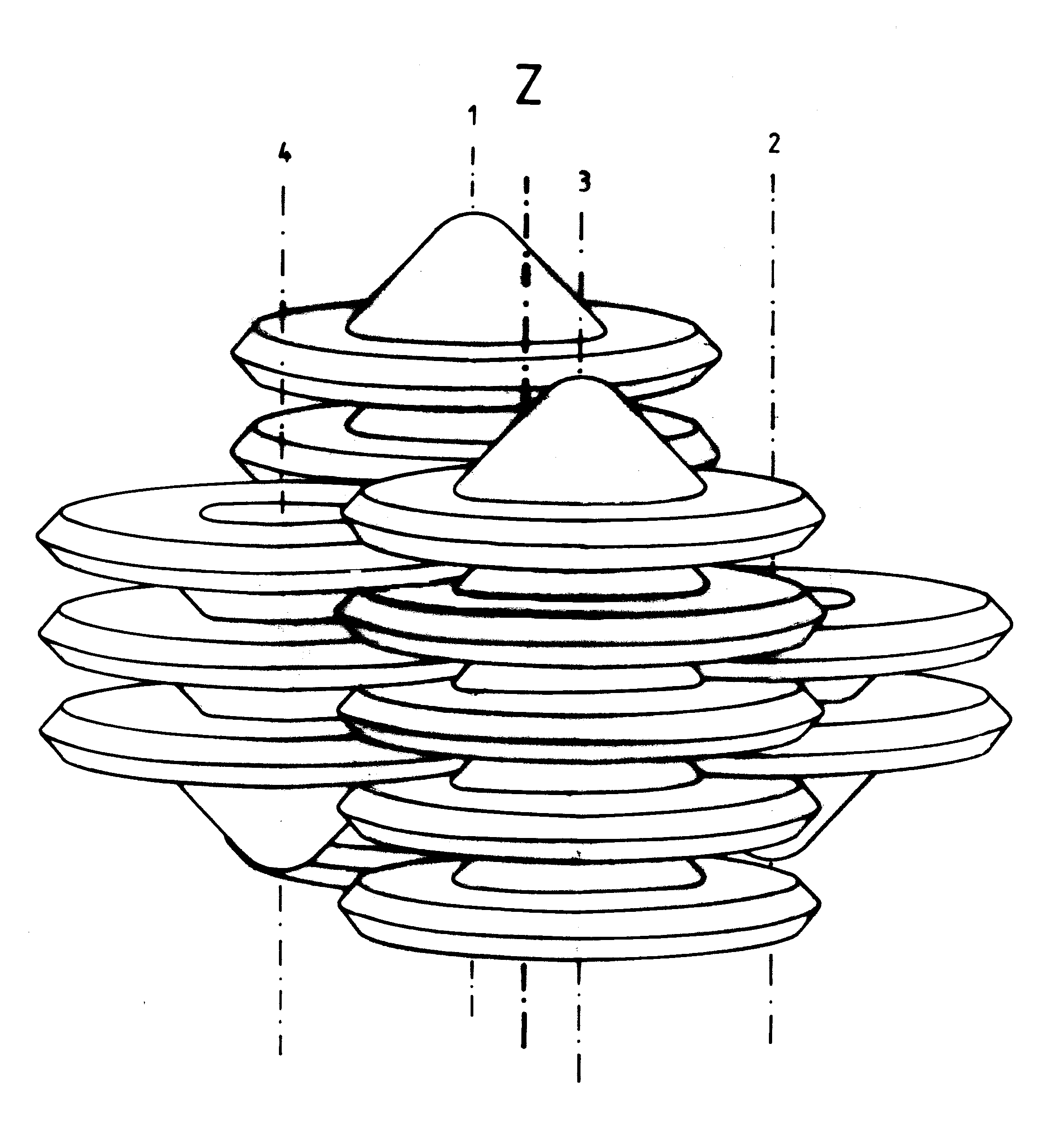 [2e] Figure G6-#5: A flying system of UFOs and Magnocraft. [2e] Figure G6-#5: A flying system of UFOs and Magnocraft.
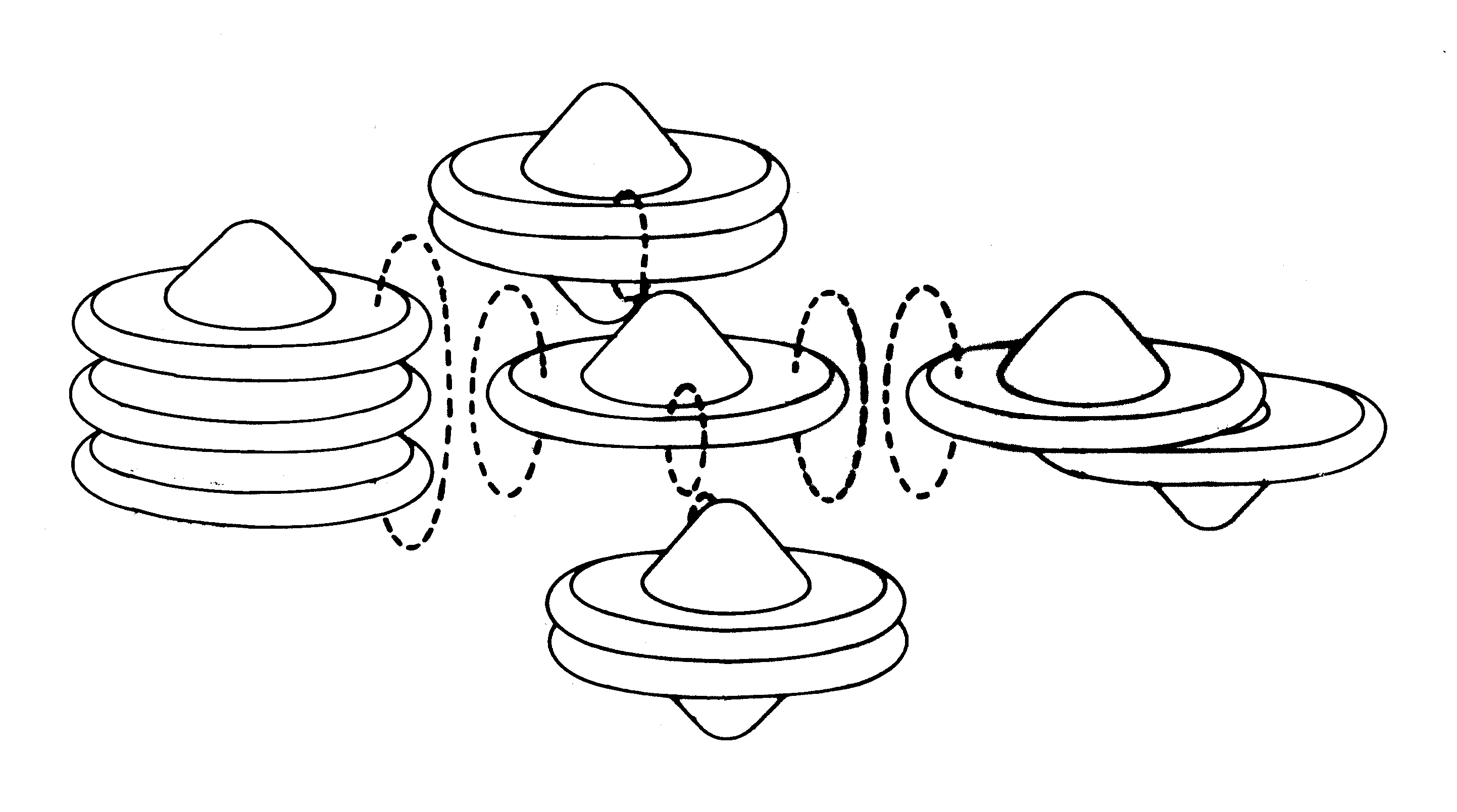 [2e] Figure G6-#6: A flying cluster of several UFOs and Magnocraft. [2e] Figure G6-#6: A flying cluster of several UFOs and Magnocraft.
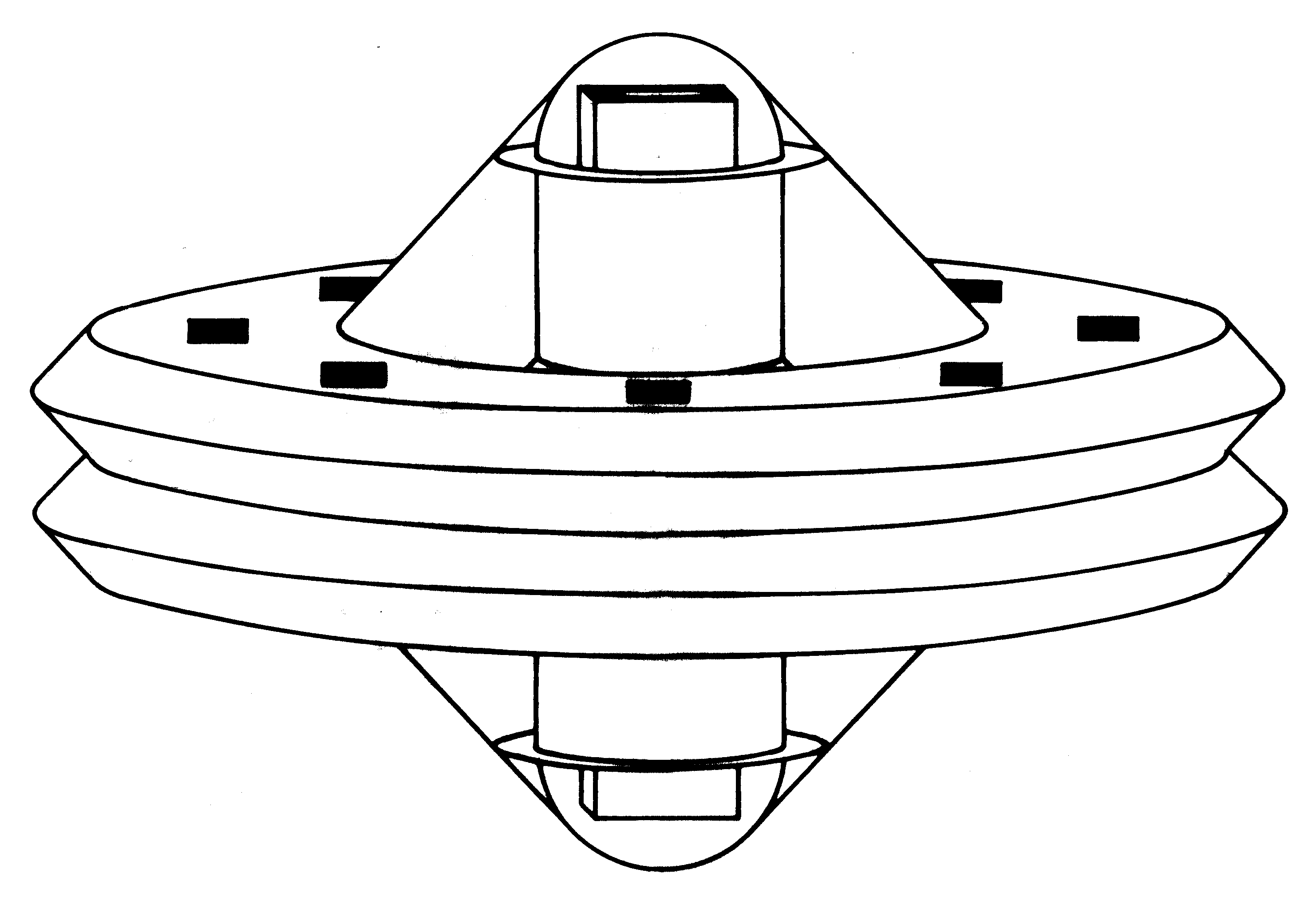 [2e] Figure G7: A spherical complex of K3 type Magnocreaft. [2e] Figure G7: A spherical complex of K3 type Magnocreaft.
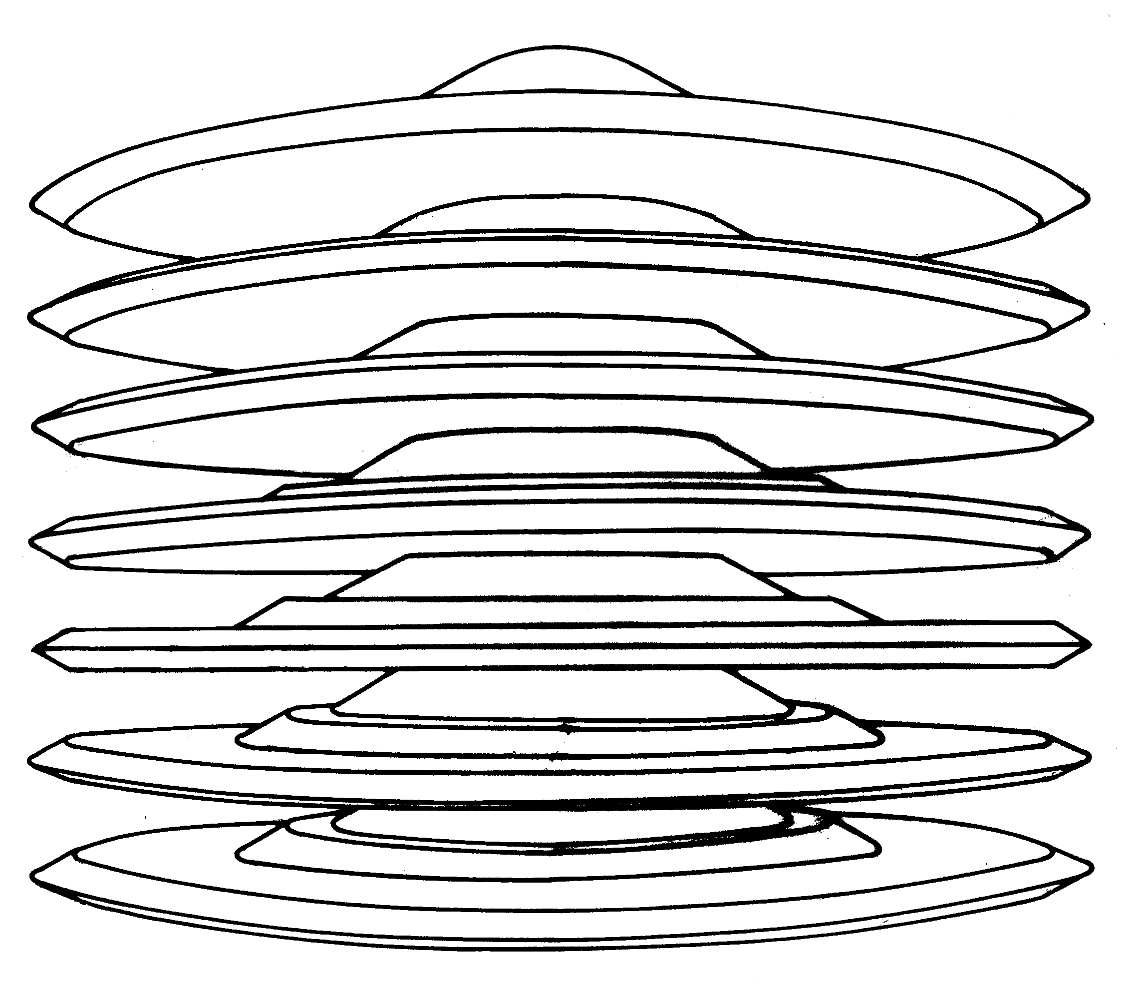 [2e] Figure G8 (a): A "stacked cigar-shaped flying complex" composed of six Magnocraft/UFOs type K6. A side view of the entire complex. [2e] Figure G8 (a): A "stacked cigar-shaped flying complex" composed of six Magnocraft/UFOs type K6. A side view of the entire complex.
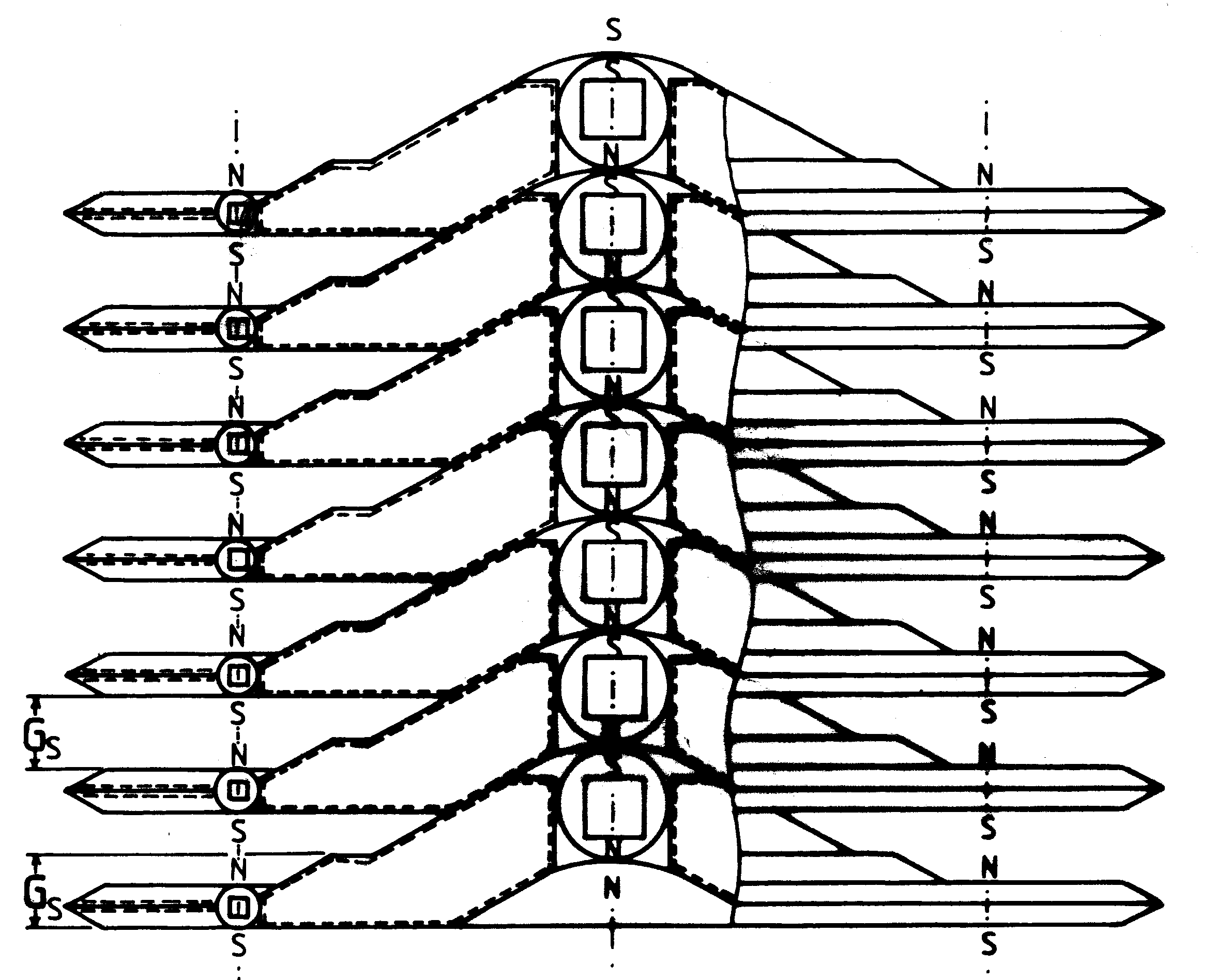 [2e] Figure G8 (b): Axial cross section showing the location of magnetic propulsors. [2e] Figure G8 (b): Axial cross section showing the location of magnetic propulsors.
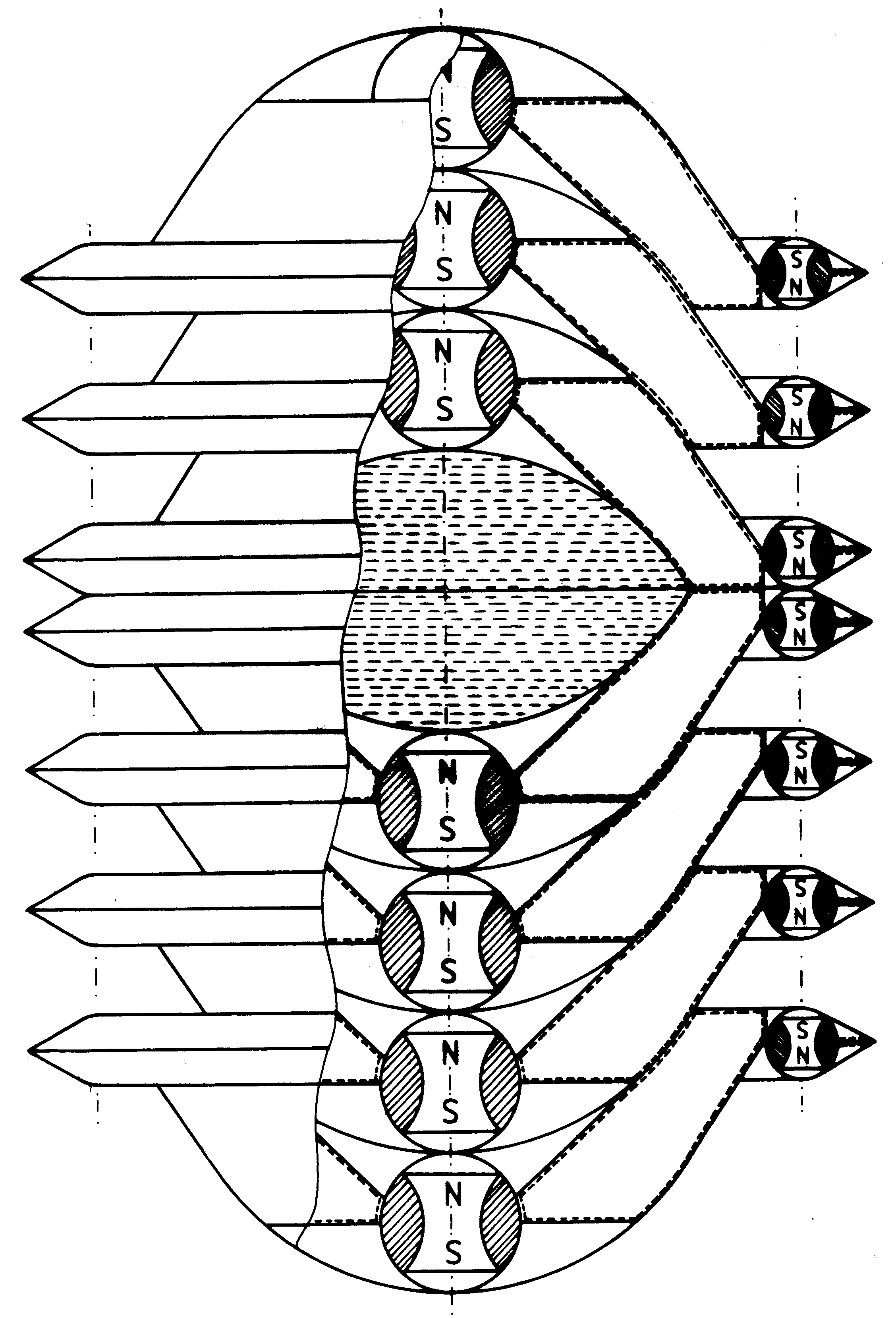 [2e] Figure G9: A double-ended cigar shaped flying complex. [2e] Figure G9: A double-ended cigar shaped flying complex.
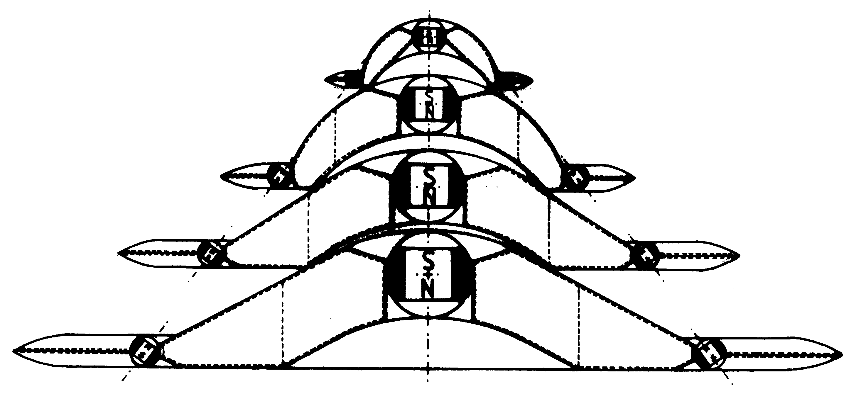 [2e] Figure G10 (a): Example of a "fir tree" shaped flying complex. (a) vertical cross section. [2e] Figure G10 (a): Example of a "fir tree" shaped flying complex. (a) vertical cross section.
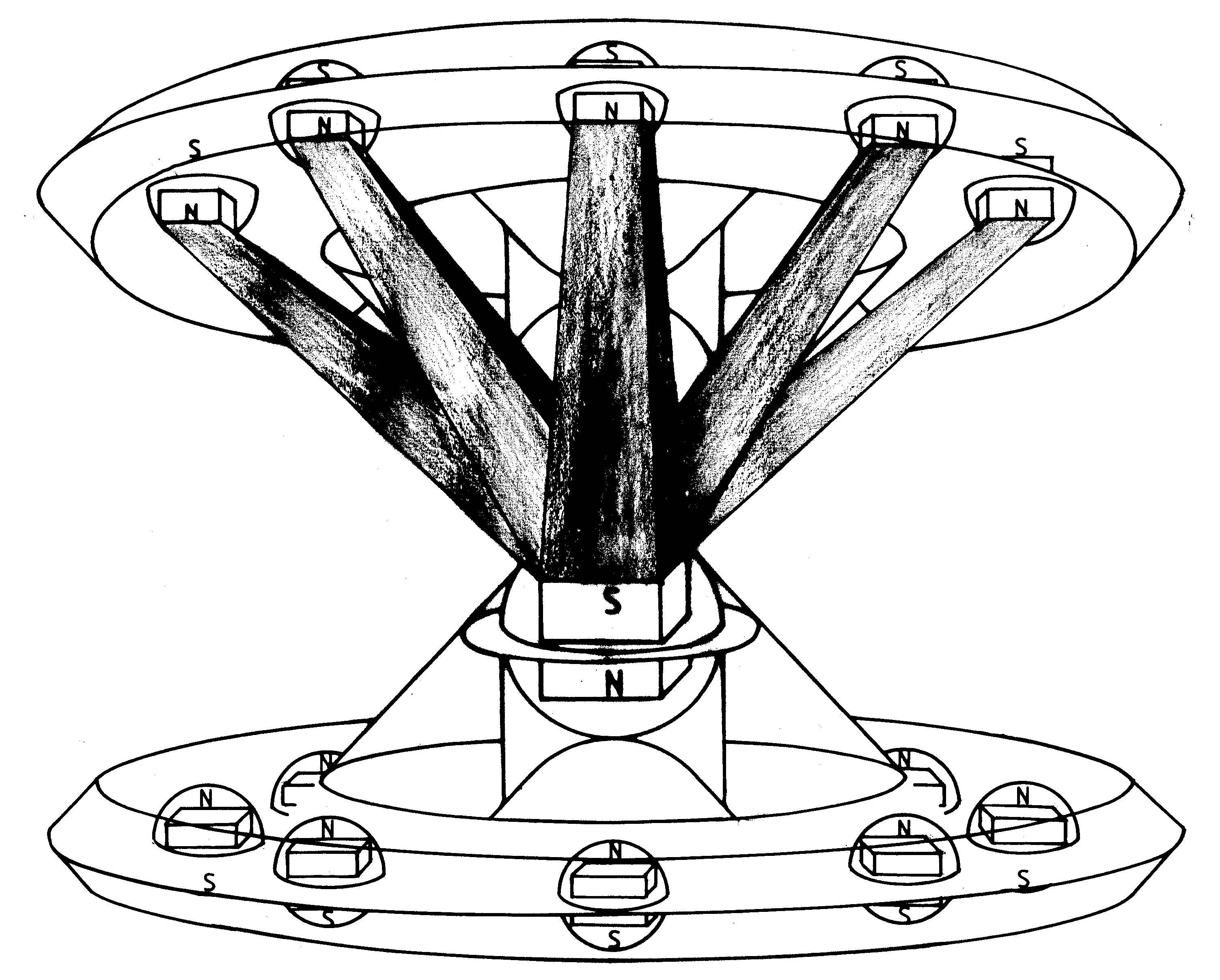
 [2e] Figure G10 (b): Side view. [2e] Figure G10 (b): Side view.
 [2e] Figure G11: A very simple semi-attached configuration of K3 type Magnocraft. [2e] Figure G11: A very simple semi-attached configuration of K3 type Magnocraft.
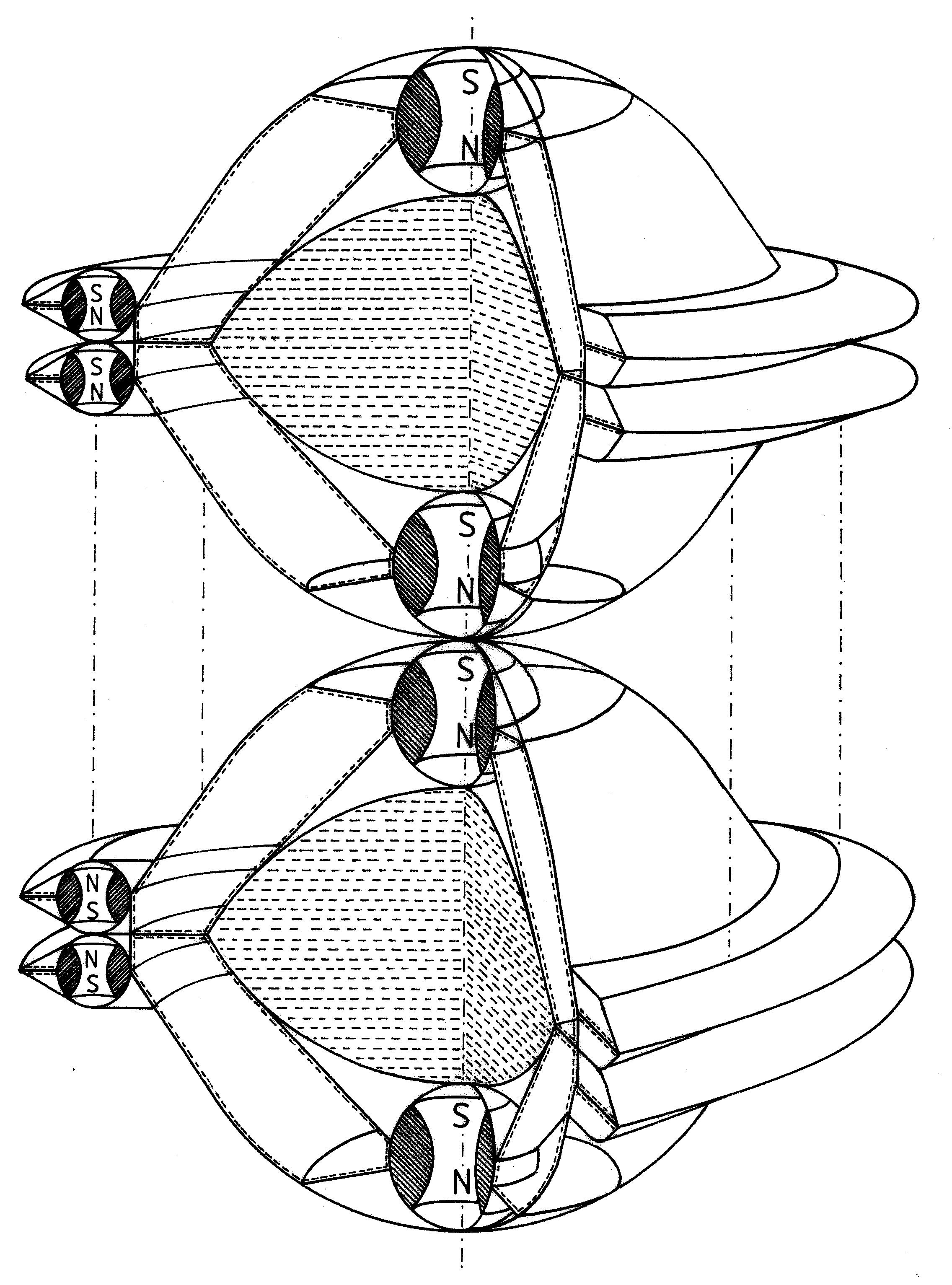 [2e] Figure G12: A "flying necklace" semi-attached configuration. [2e] Figure G12: A "flying necklace" semi-attached configuration.
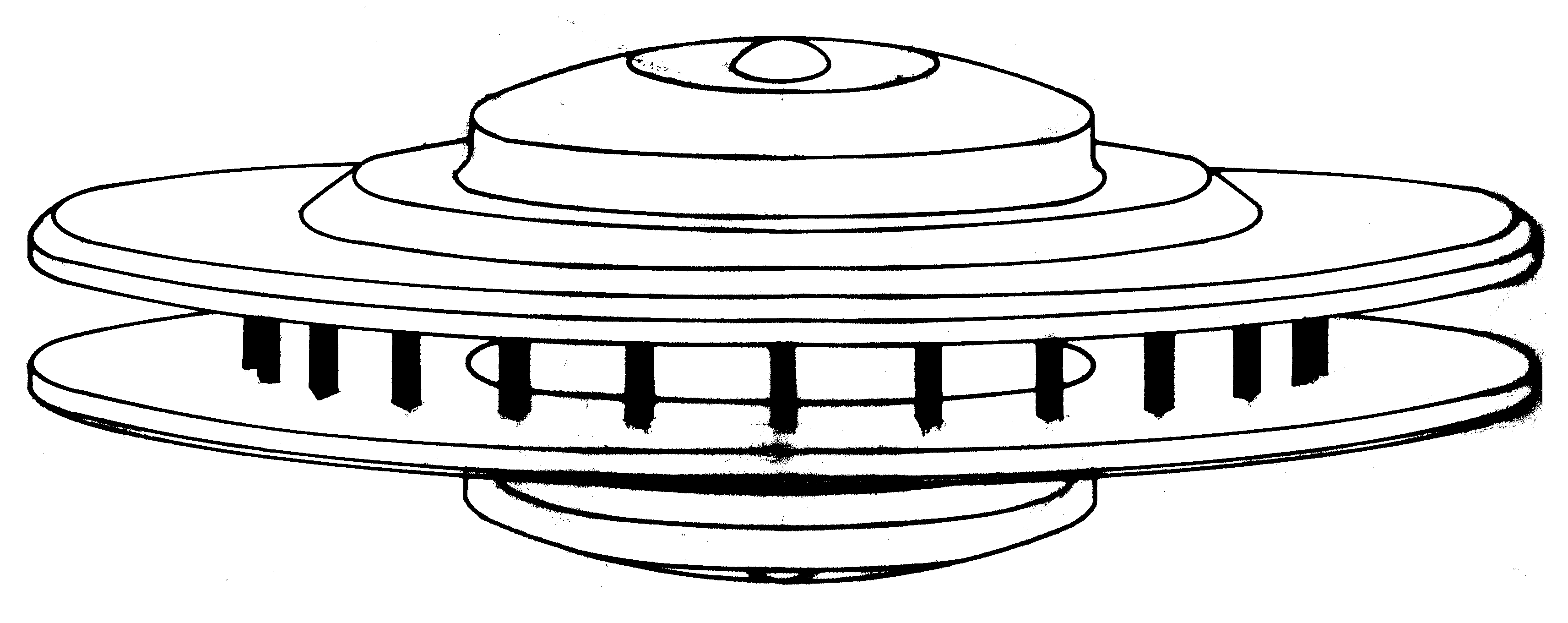 [2e] Figure G13 (high): An example of K7 detached configuration. (a) External appearence. [2e] Figure G13 (high): An example of K7 detached configuration. (a) External appearence.
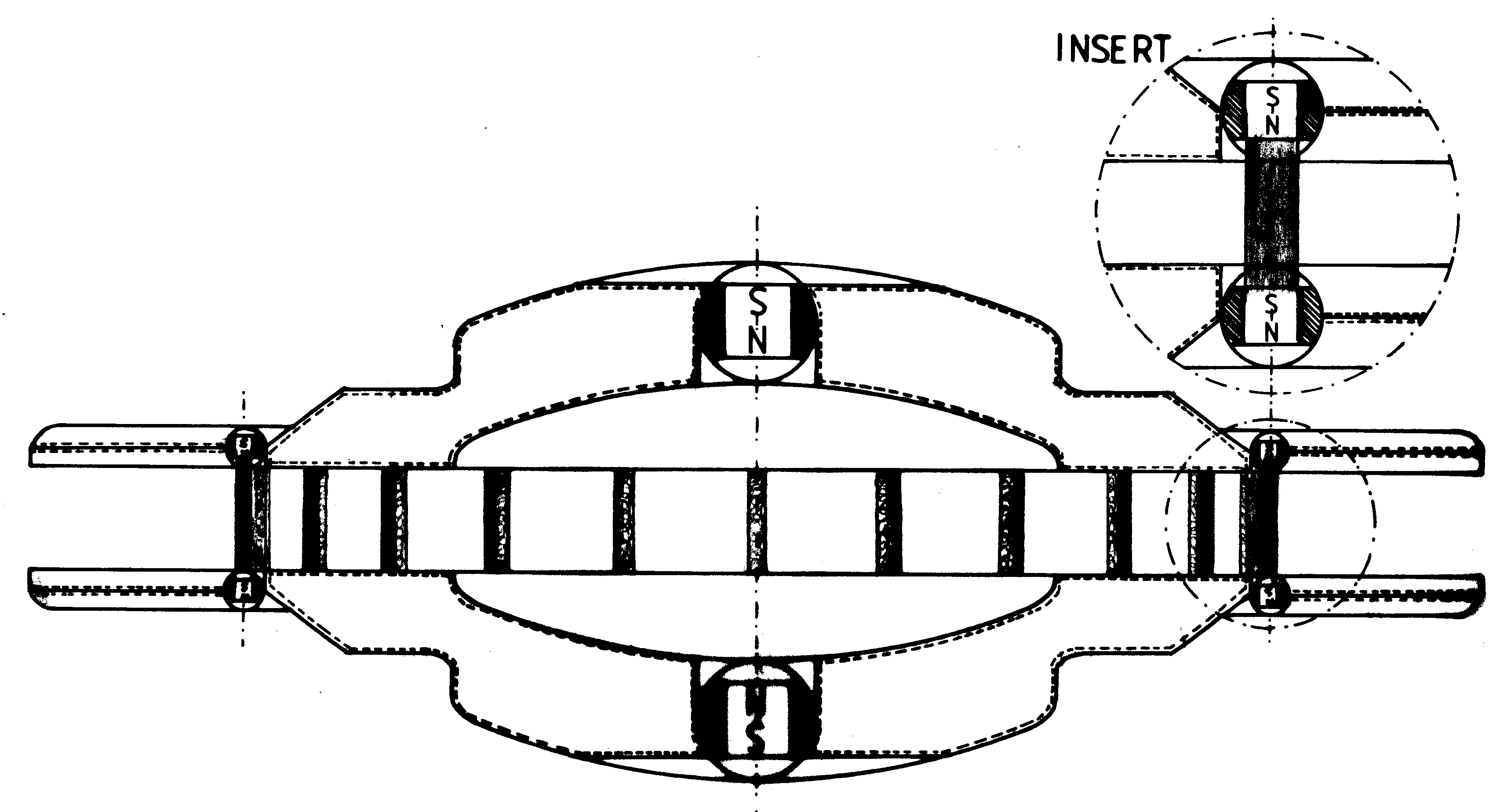 [2e] Figure G13 (low): Vertical cross-section shopwing the location of propulsors. [2e] Figure G13 (low): Vertical cross-section shopwing the location of propulsors.
 [2e] Figure G14: An example of a carrier platform. [2e] Figure G14: An example of a carrier platform.
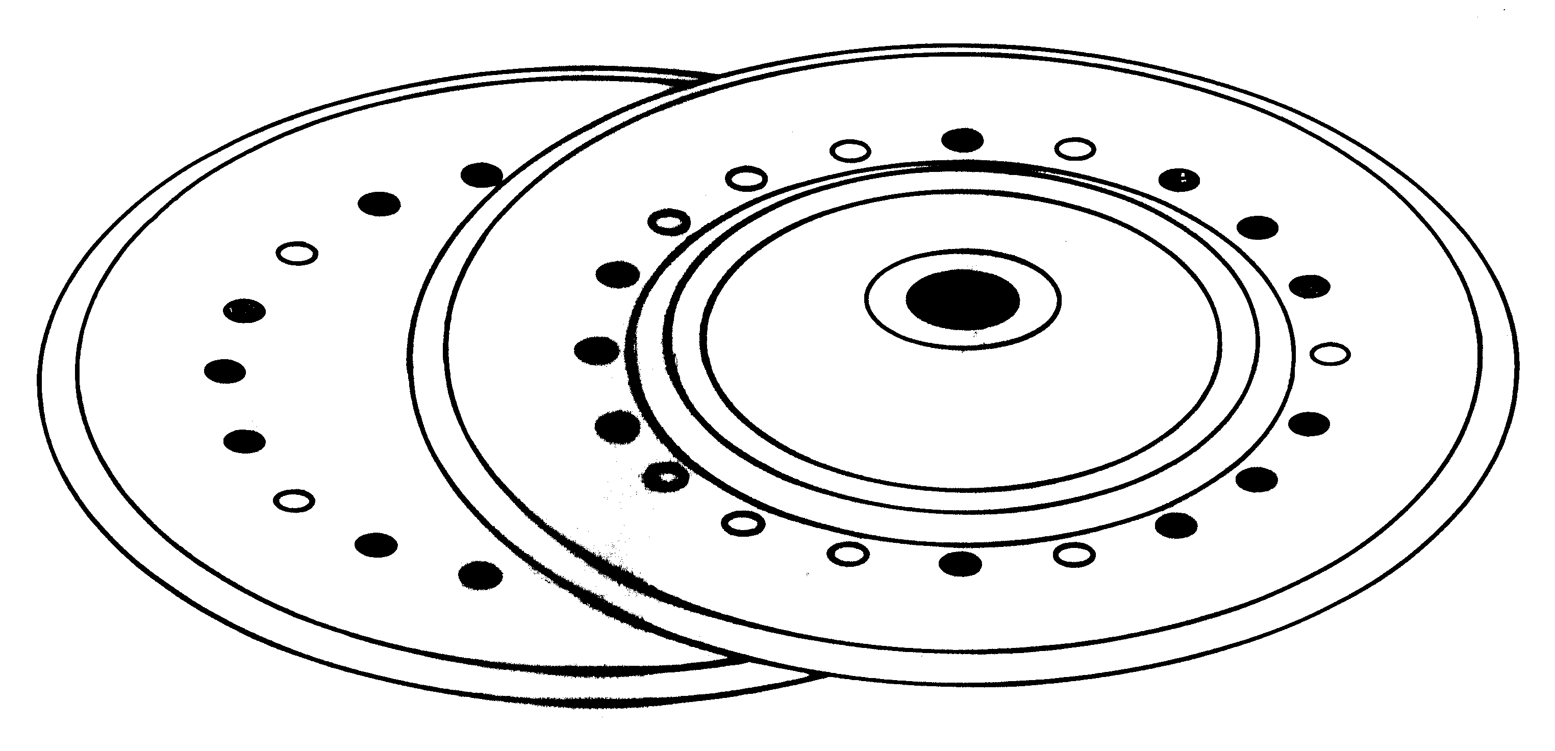 [2e] Figure G15: A "zig-zag" carrier configuration. [2e] Figure G15: A "zig-zag" carrier configuration.
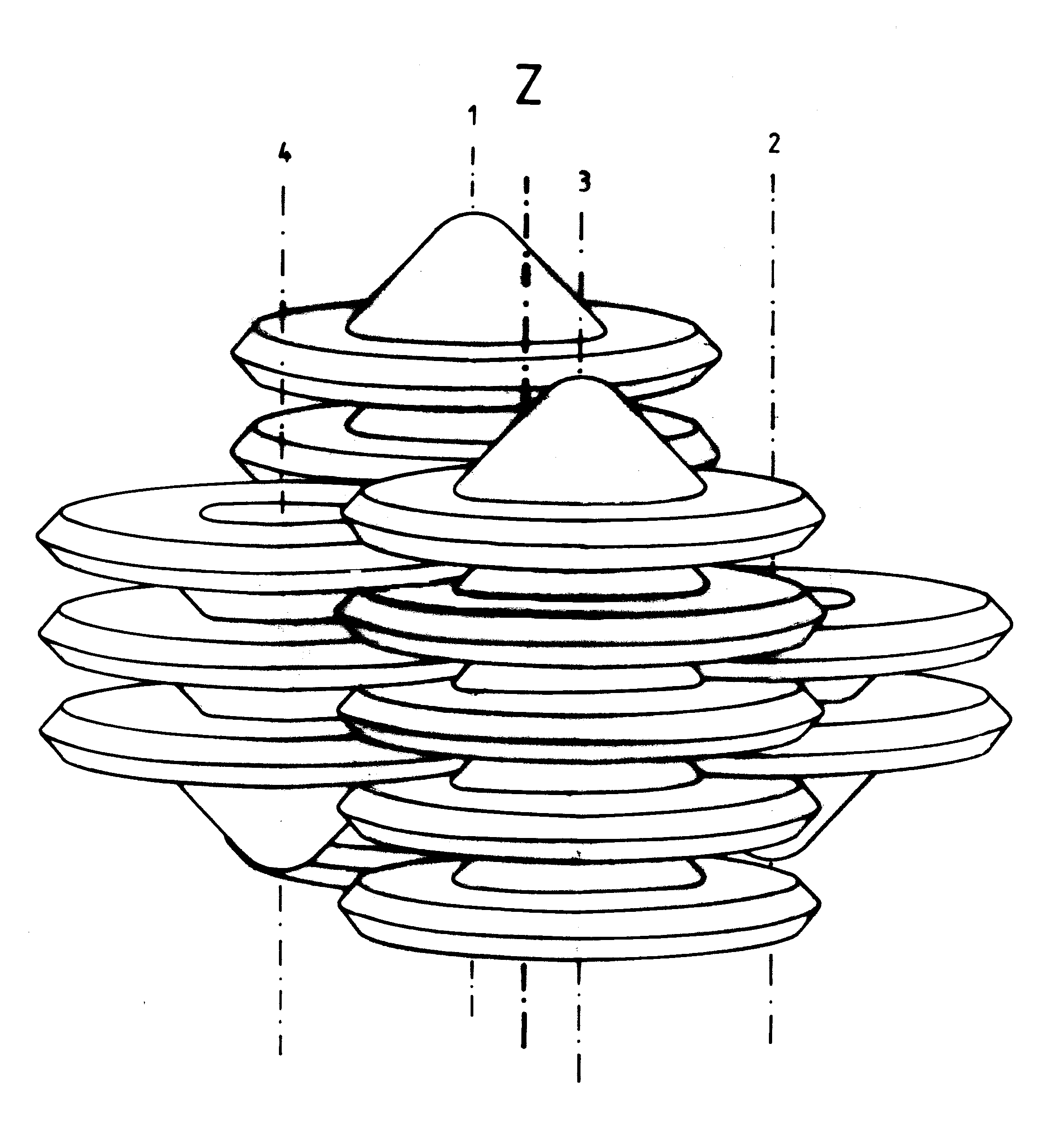 [2e] Figure G16 (a): Examples of flying systems. (a) A single cell composed of 16 K3 type Magnocraft. [2e] Figure G16 (a): Examples of flying systems. (a) A single cell composed of 16 K3 type Magnocraft.
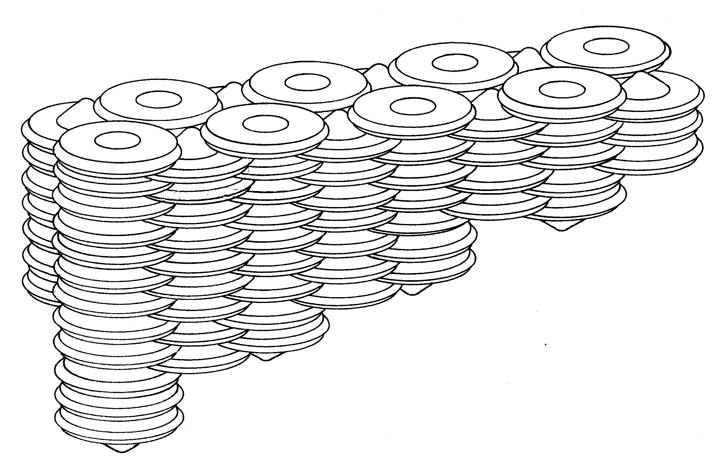 [2e] Figure G16 (b): Flying system shaped as "flutes". [2e] Figure G16 (b): Flying system shaped as "flutes".
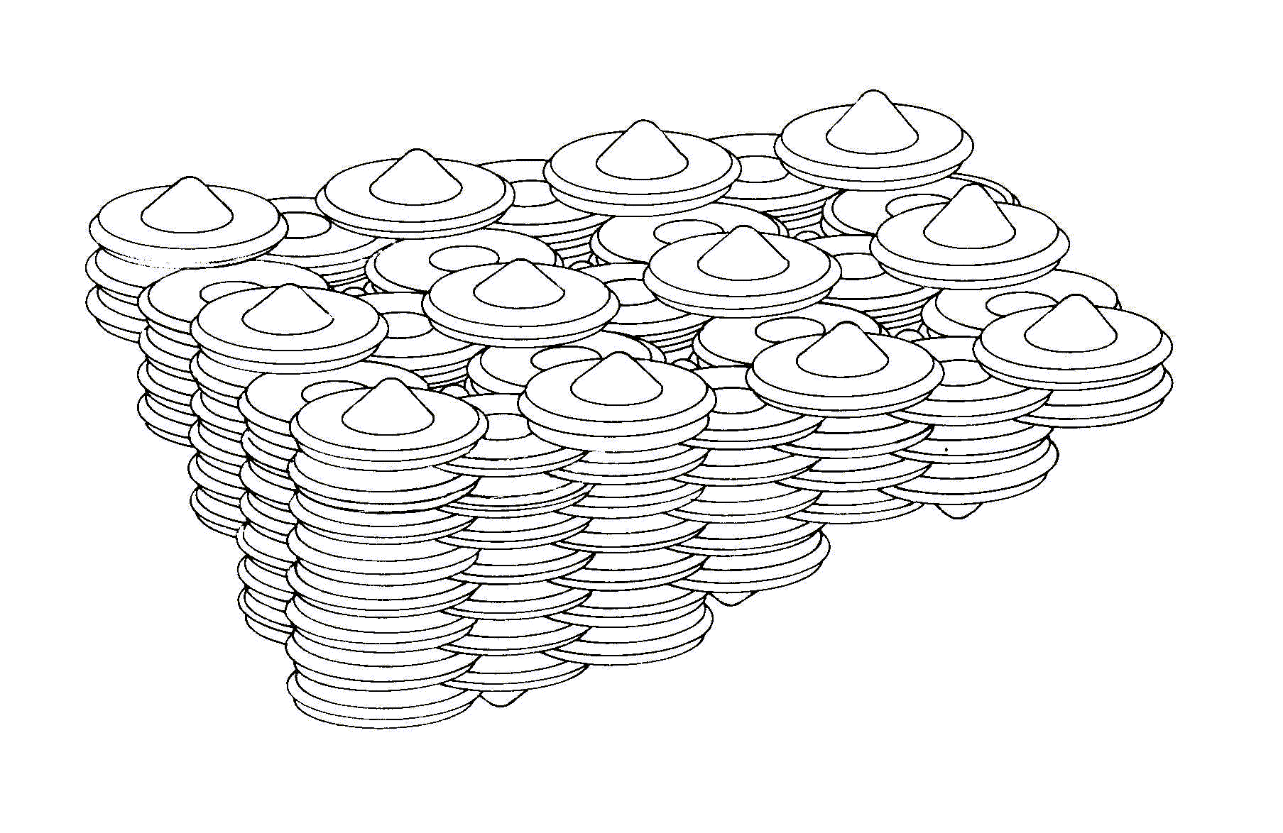 [2e] Figure G16 (c): Flying system shaped as a "honeycomb". [2e] Figure G16 (c): Flying system shaped as a "honeycomb".
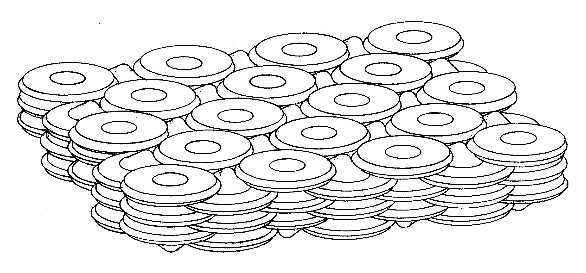 [2e] Figure G16 (d): Flying system shaped as a "platform". [2e] Figure G16 (d): Flying system shaped as a "platform".
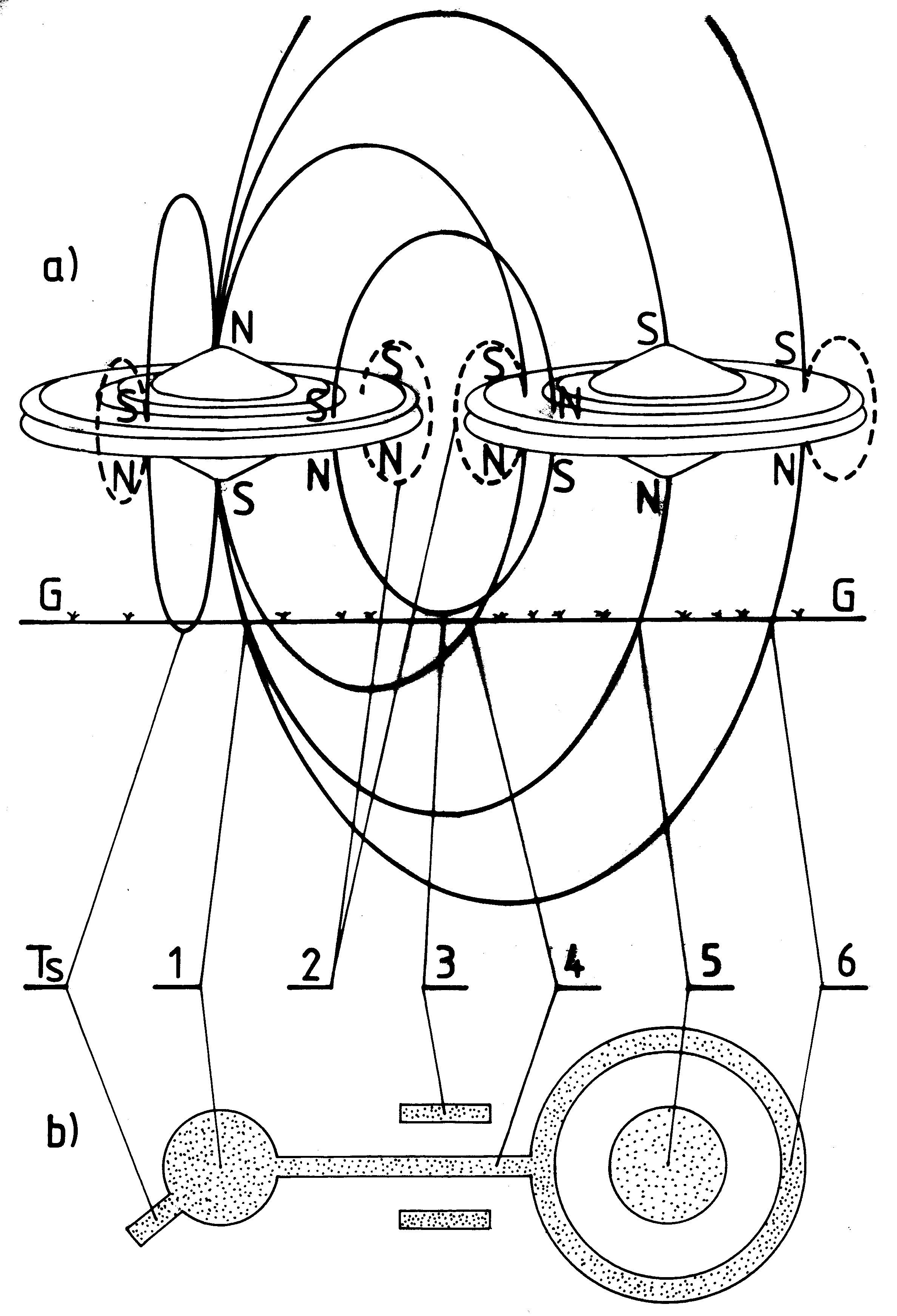 [2e] Figure G17: An example of a flying cluster composed of two spherical complexes type K6. [2e] Figure G17: An example of a flying cluster composed of two spherical complexes type K6.
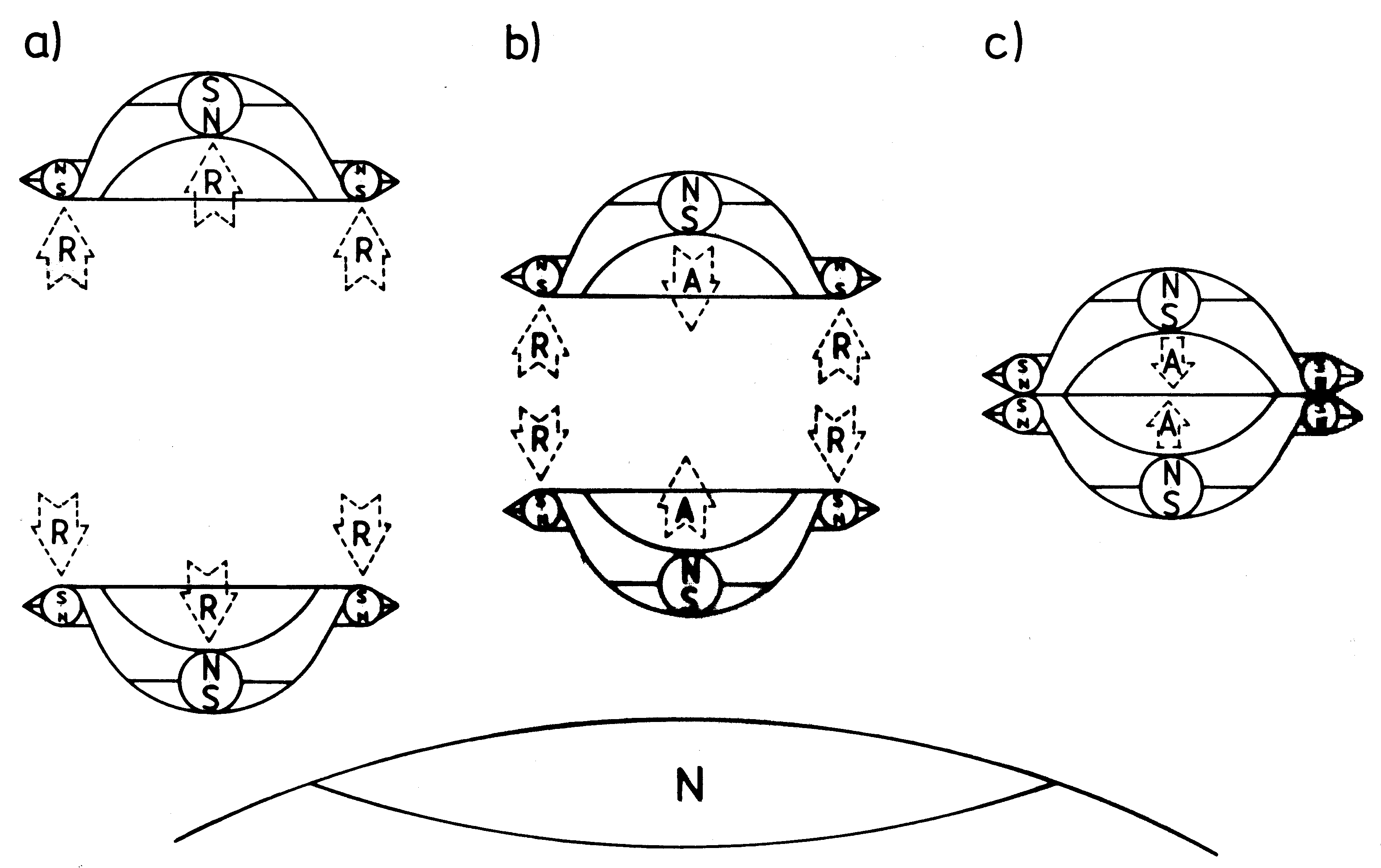 [2e] Figure G18: Coupling through a detached configuration. [2e] Figure G18: Coupling through a detached configuration.
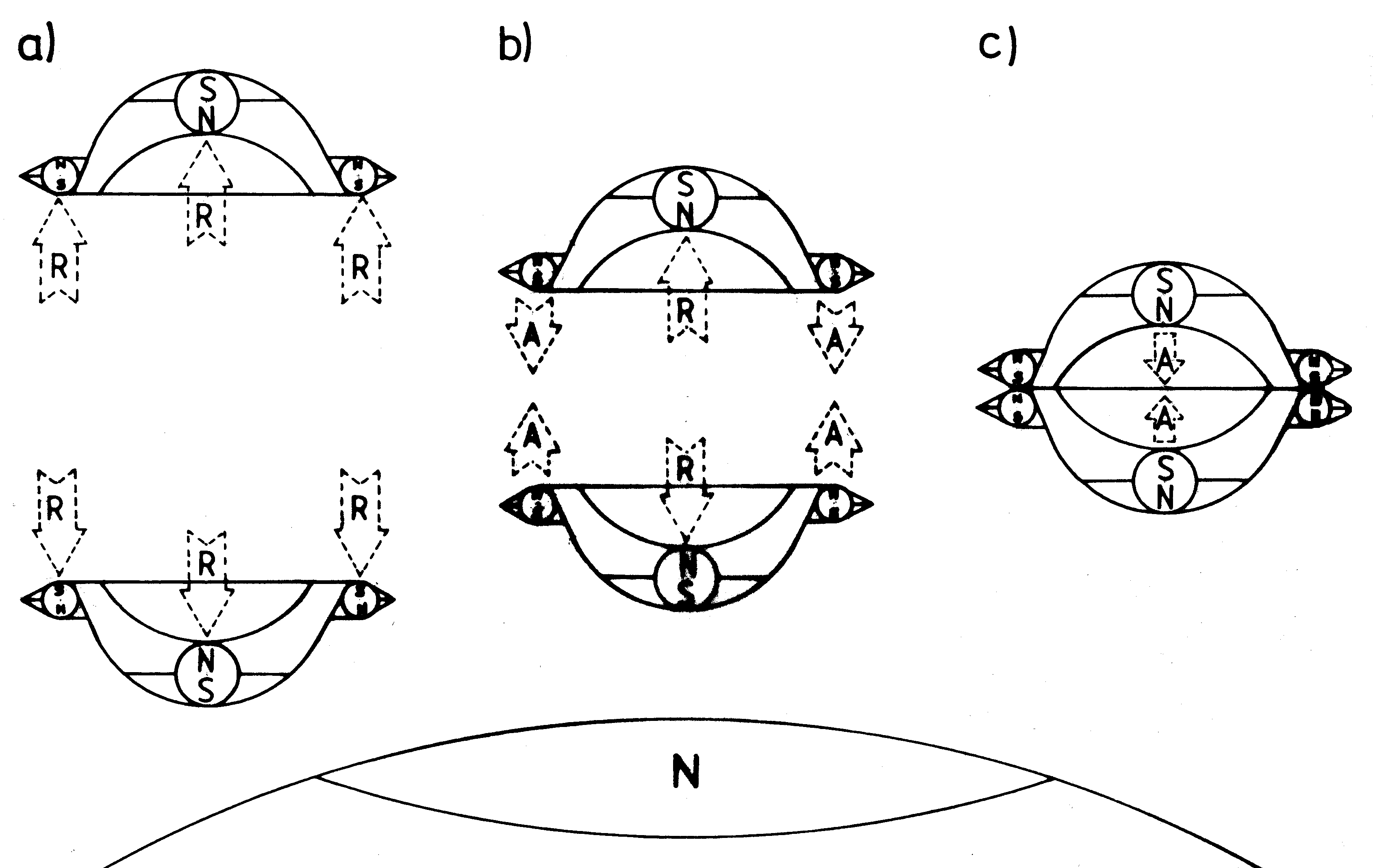 [2e] Figure G19: Coupling through a semi-attached configuration. [2e] Figure G19: Coupling through a semi-attached configuration.
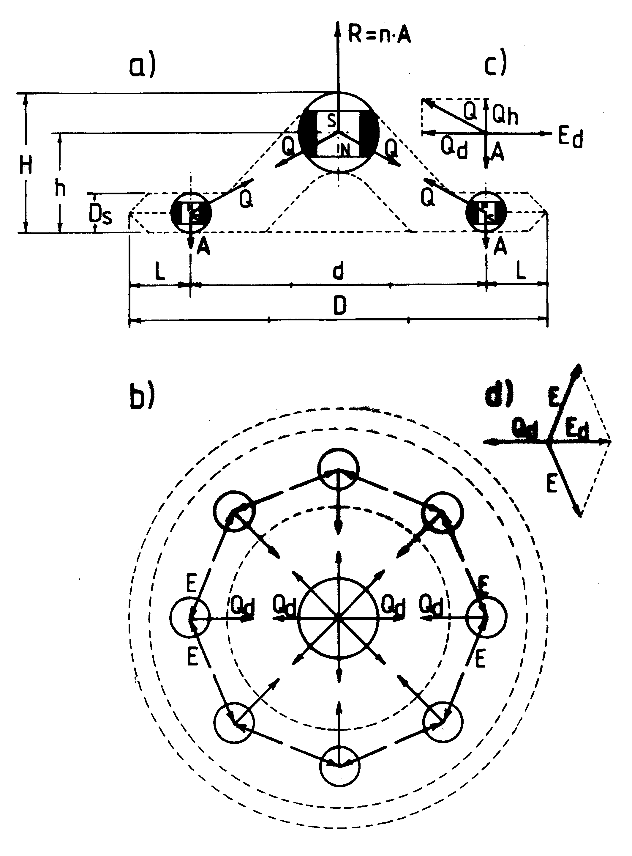 [2e] Figure G20: Force interactions acting in Magnocraft. [2e] Figure G20: Force interactions acting in Magnocraft.
 [2e] Figure G21: A top view of one cell of flying systems. [2e] Figure G21: A top view of one cell of flying systems.
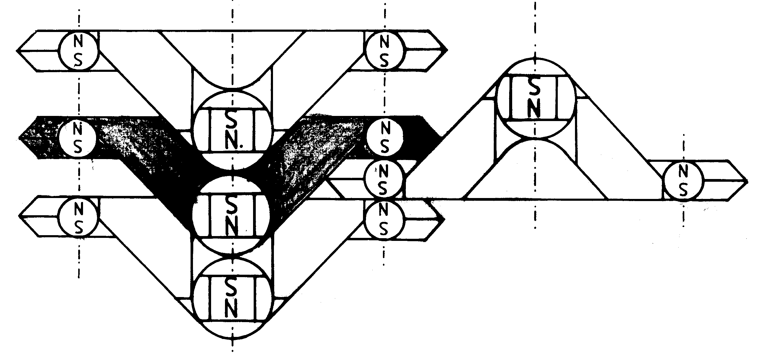 [2e] Figure G22 (a): Meshing of flanges in flying systems. (a) K3 type Magnocraft. [2e] Figure G22 (a): Meshing of flanges in flying systems. (a) K3 type Magnocraft.
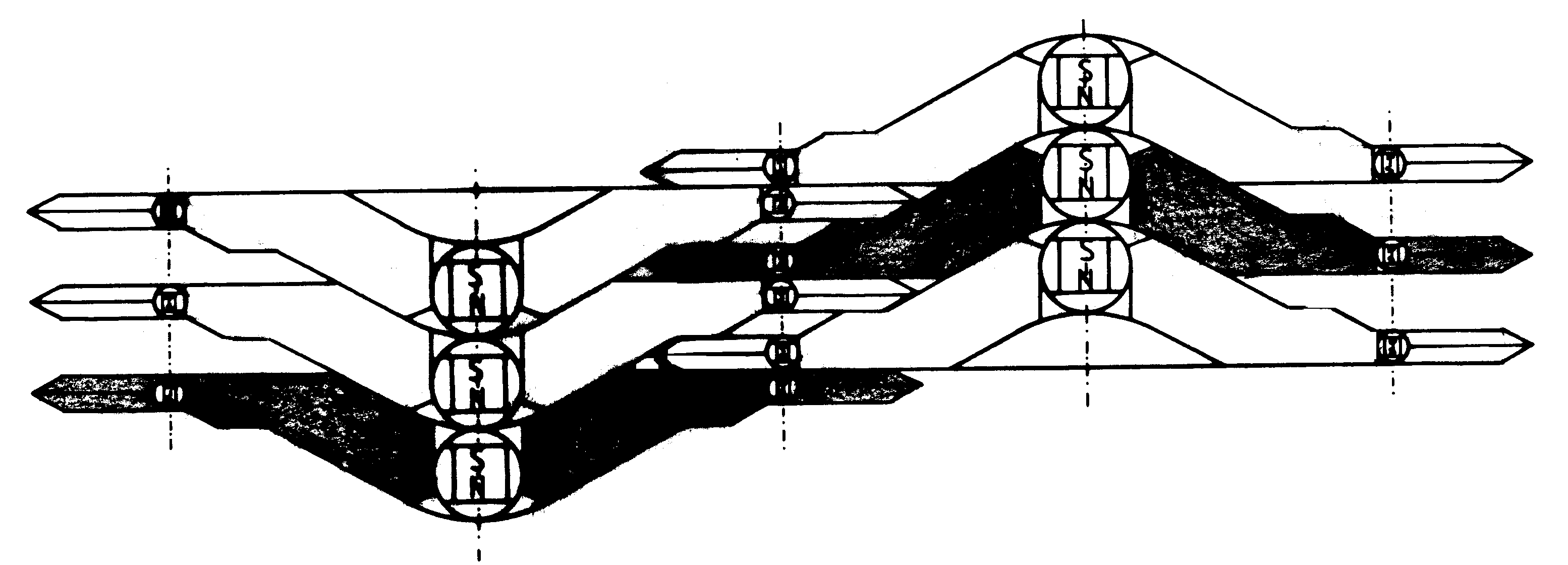 [2e] Figure G22 (b): Two cigar of K6 type mutually mesched. [2e] Figure G22 (b): Two cigar of K6 type mutually mesched.
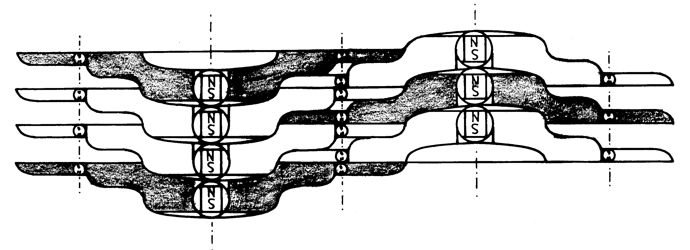 [2e] Figure G22 (c): two cigar of K7 type mutually mesched. [2e] Figure G22 (c): two cigar of K7 type mutually mesched.
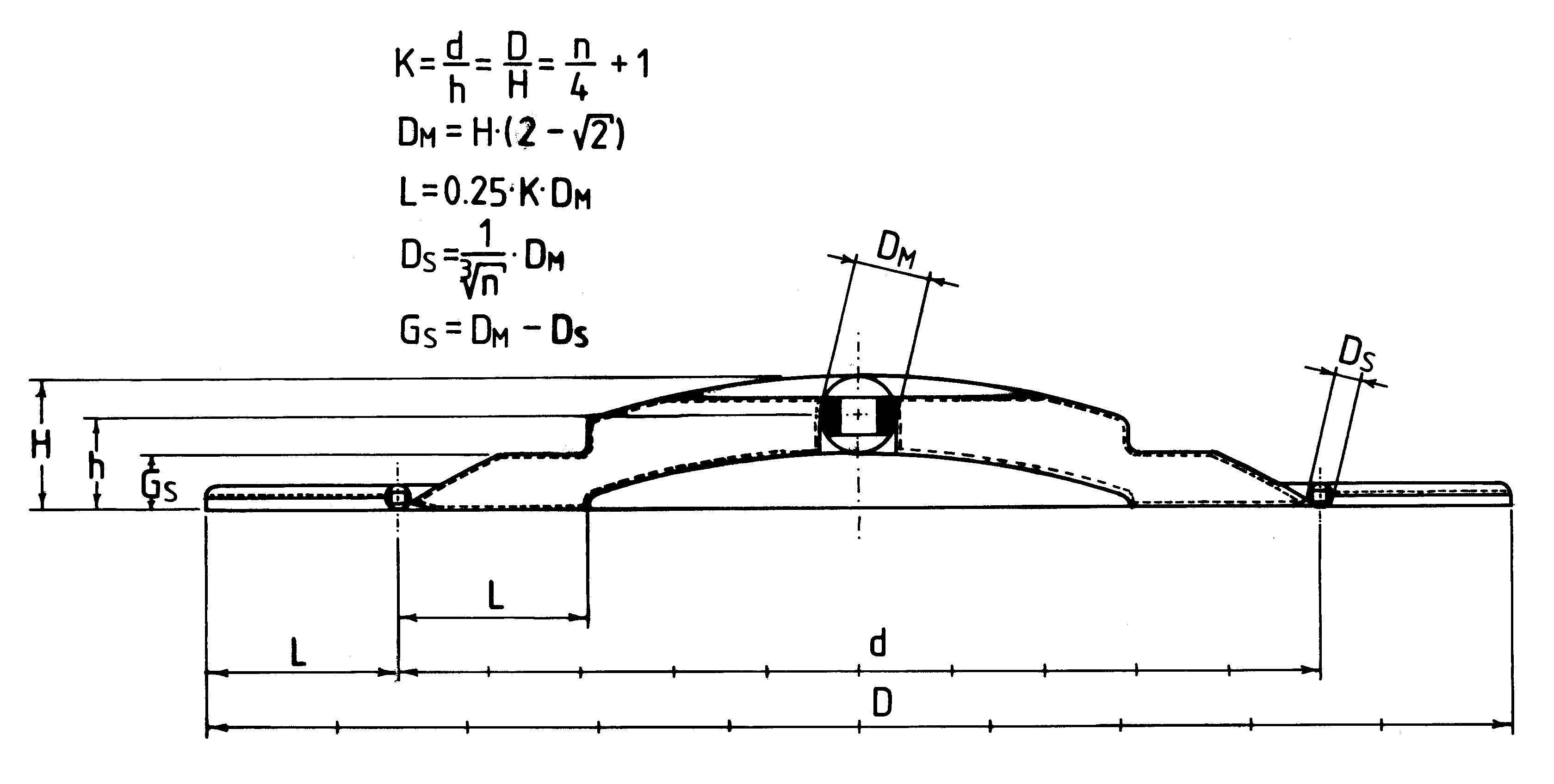 [2e] Figure G23: Equations describing shape and dimensions of the Magnocraft. [2e] Figure G23: Equations describing shape and dimensions of the Magnocraft.
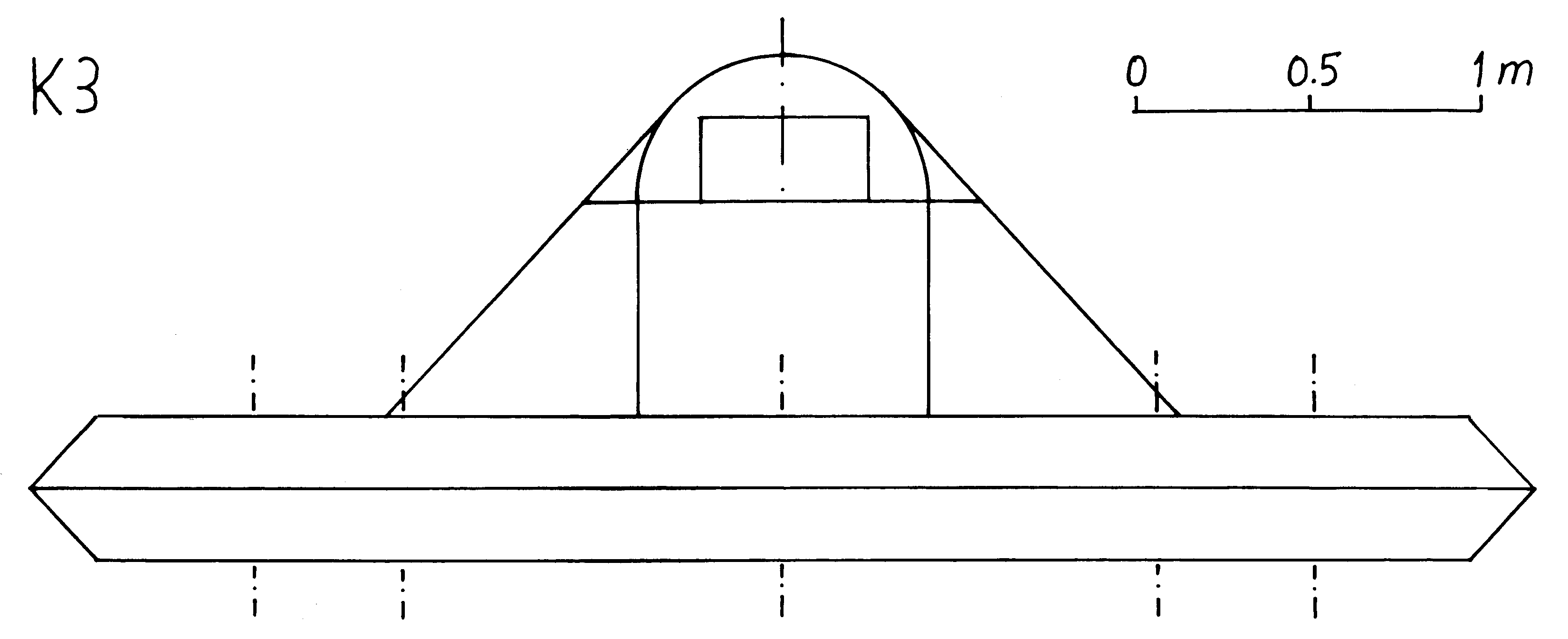 [2e] Figure G24 (a-K3): Side outlines of eight types of Magnocraft. (a) K3 type. [2e] Figure G24 (a-K3): Side outlines of eight types of Magnocraft. (a) K3 type.
 [2e] Figure G24 (a-K4): K4 type. [2e] Figure G24 (a-K4): K4 type.
 [2e] Figure G24 (a-K5): K5 type. [2e] Figure G24 (a-K5): K5 type.
 [2e] Figure G24 (a-K6): K6 type. [2e] Figure G24 (a-K6): K6 type.
 [2e] Figure G24 (b-K7): K7 type. [2e] Figure G24 (b-K7): K7 type.
 [2e] Figure G24 (b-K8): K8 type. [2e] Figure G24 (b-K8): K8 type.
 [2e] Figure G24 (b-K9): K9 type. [2e] Figure G24 (b-K9): K9 type.
 [2e] Figure G24 (b-K10): K10 type. [2e] Figure G24 (b-K10): K10 type.
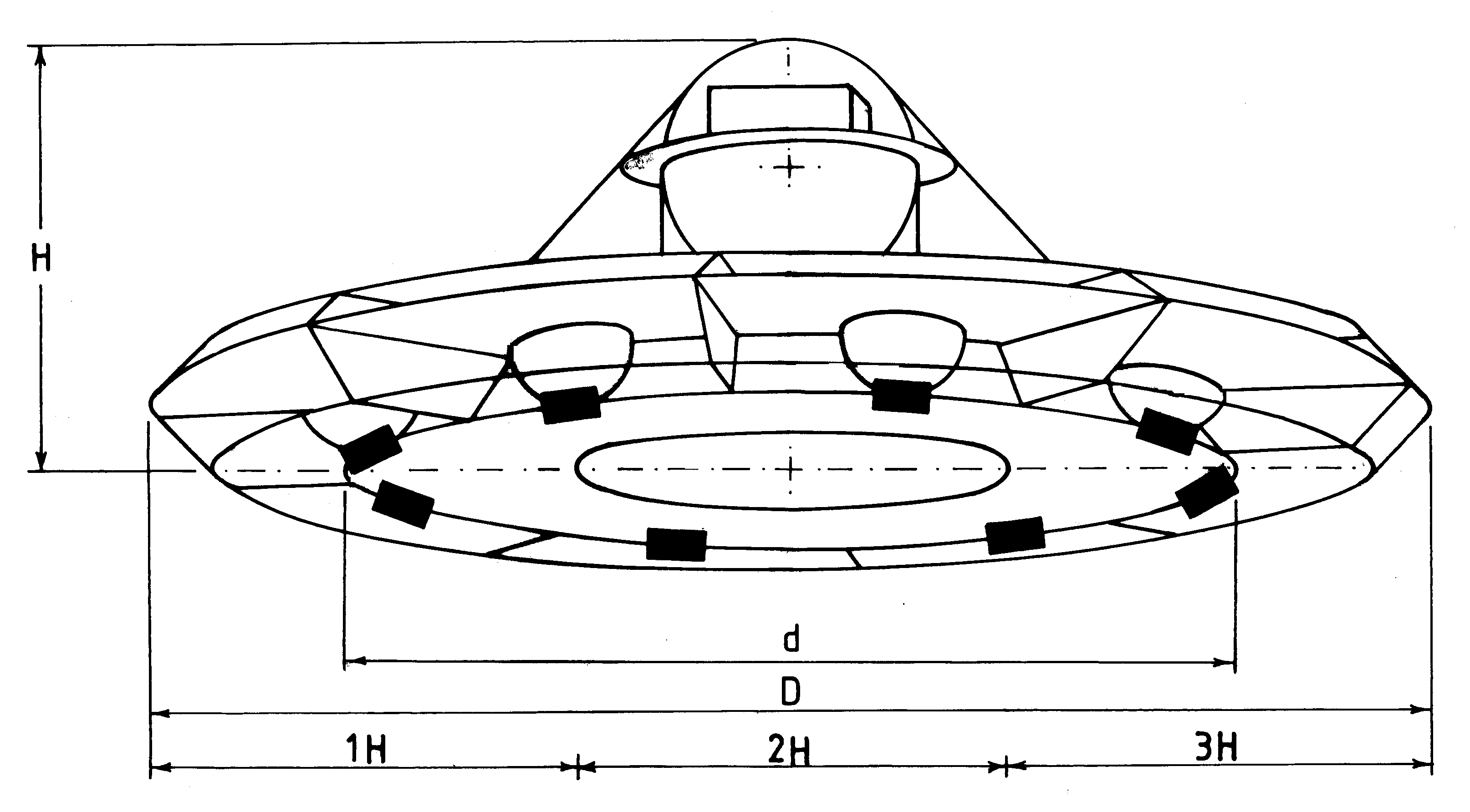 [2e] Figure G25: Methods of identifying the magnocraft's type. [2e] Figure G25: Methods of identifying the magnocraft's type.
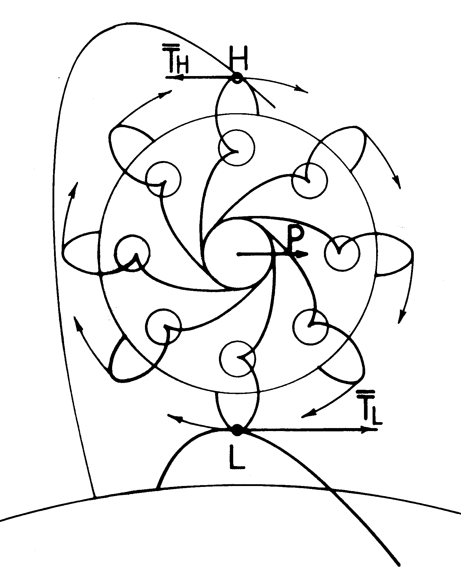 [2e] Figure G26: The creation of latitudinal thrust force. [2e] Figure G26: The creation of latitudinal thrust force.
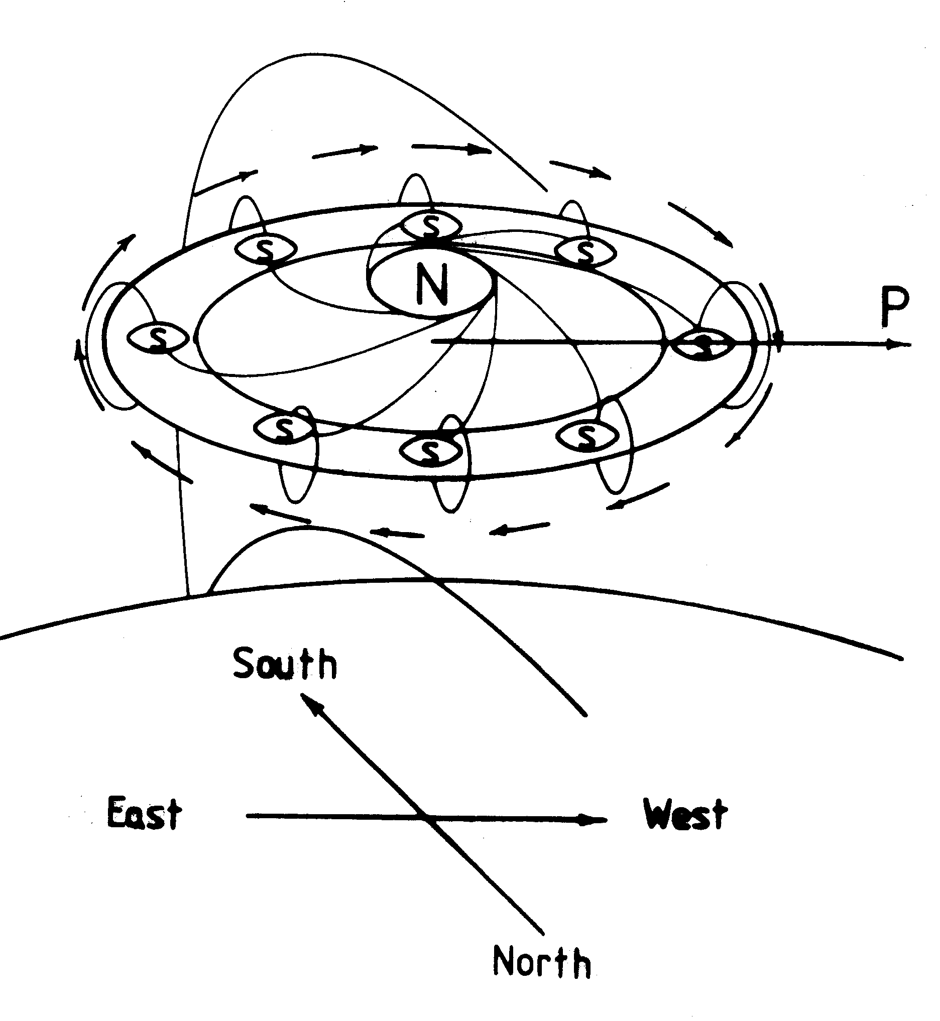 [2e] Figure G27: The "rolling sphere rule" for determing the flight direction. [2e] Figure G27: The "rolling sphere rule" for determing the flight direction.
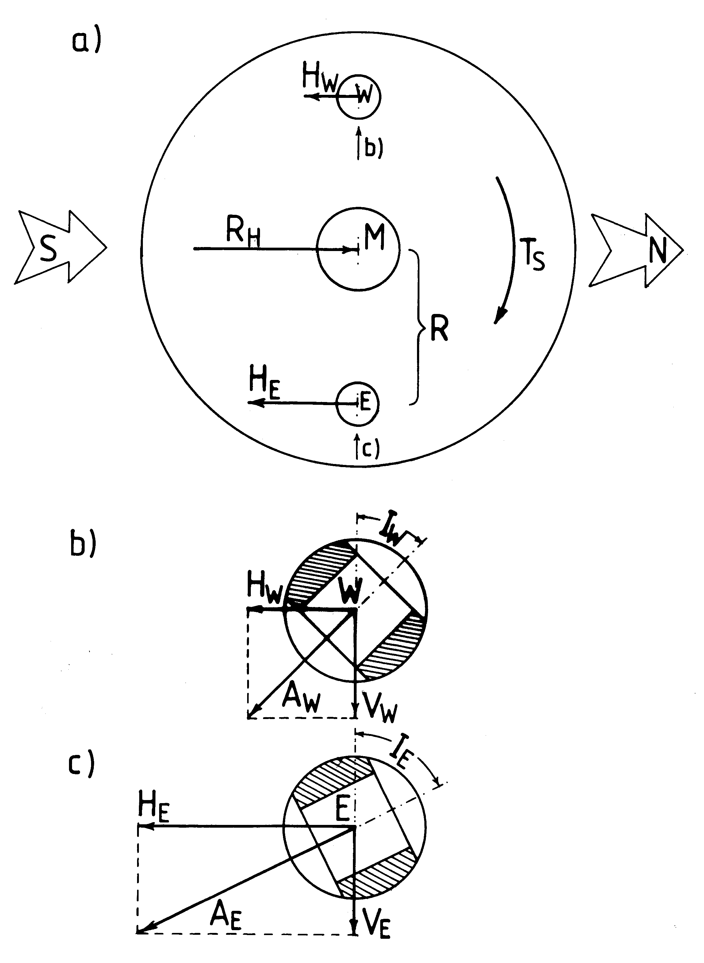 [2e] Figure G28: The counteracting of the magnetic whirl. [2e] Figure G28: The counteracting of the magnetic whirl.
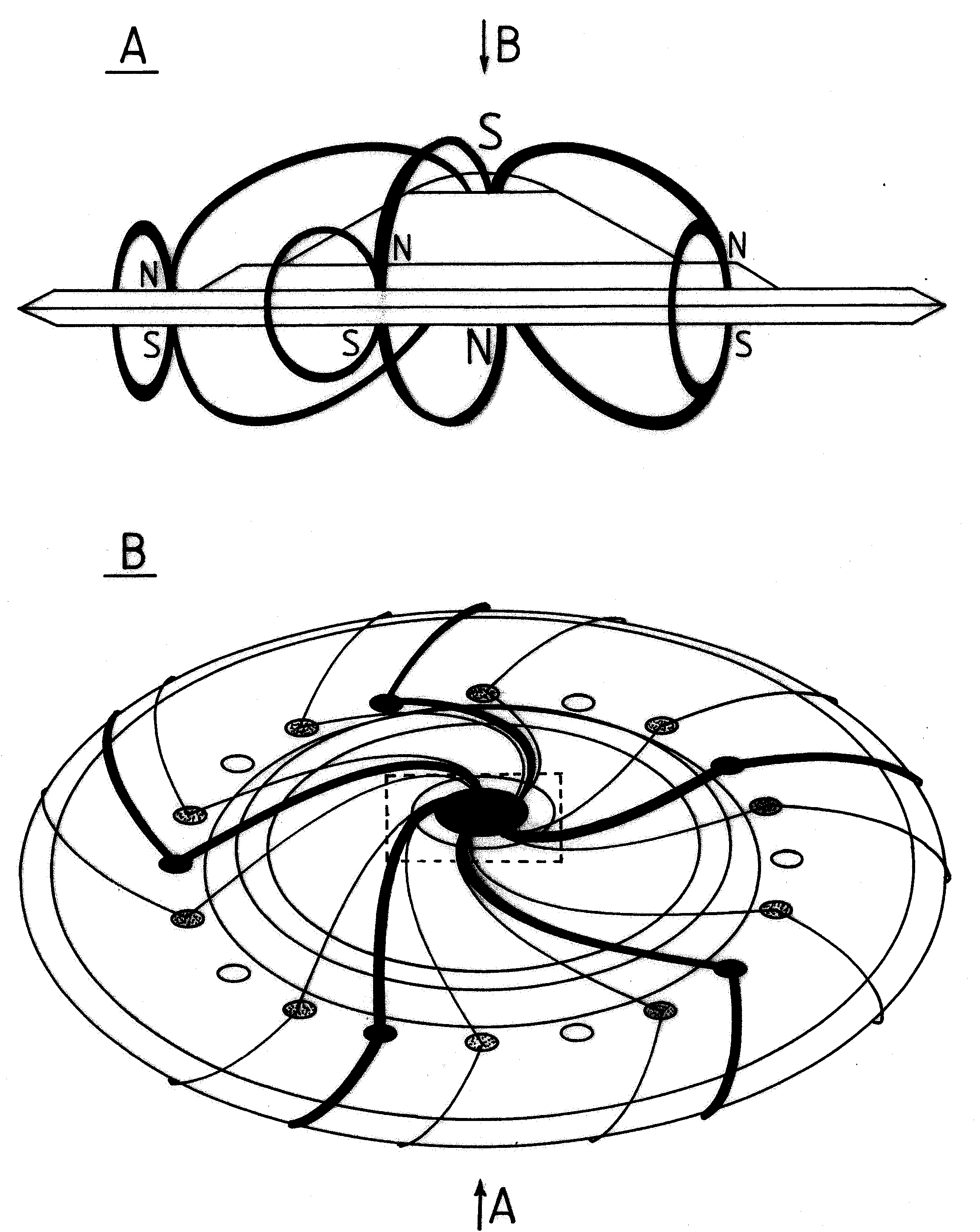 [2e] Figure G29: Magnetic circuits and magnetic whirl. The formation of magnetic circuits by propulsion system of Magnocraft. [2e] Figure G29: Magnetic circuits and magnetic whirl. The formation of magnetic circuits by propulsion system of Magnocraft.
 [2e] Figure G30 (a): The spinning circuits of K6 type Magnocraft. (a) The vertical cross-section. [2e] Figure G30 (a): The spinning circuits of K6 type Magnocraft. (a) The vertical cross-section.
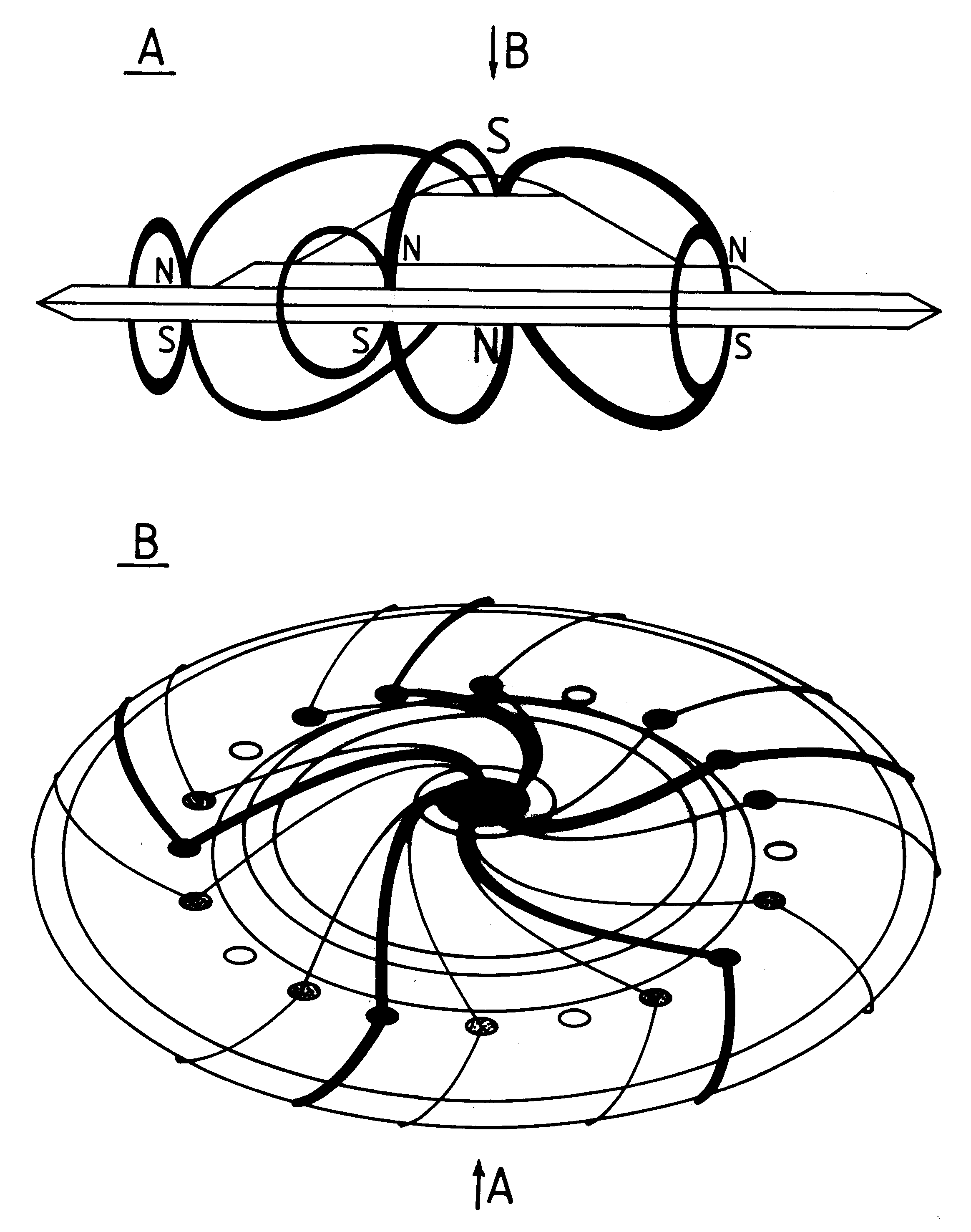 [2e] Figure G30 (bc): Side view showing magnetic circuits. [2e] Figure G30 (bc): Side view showing magnetic circuits.
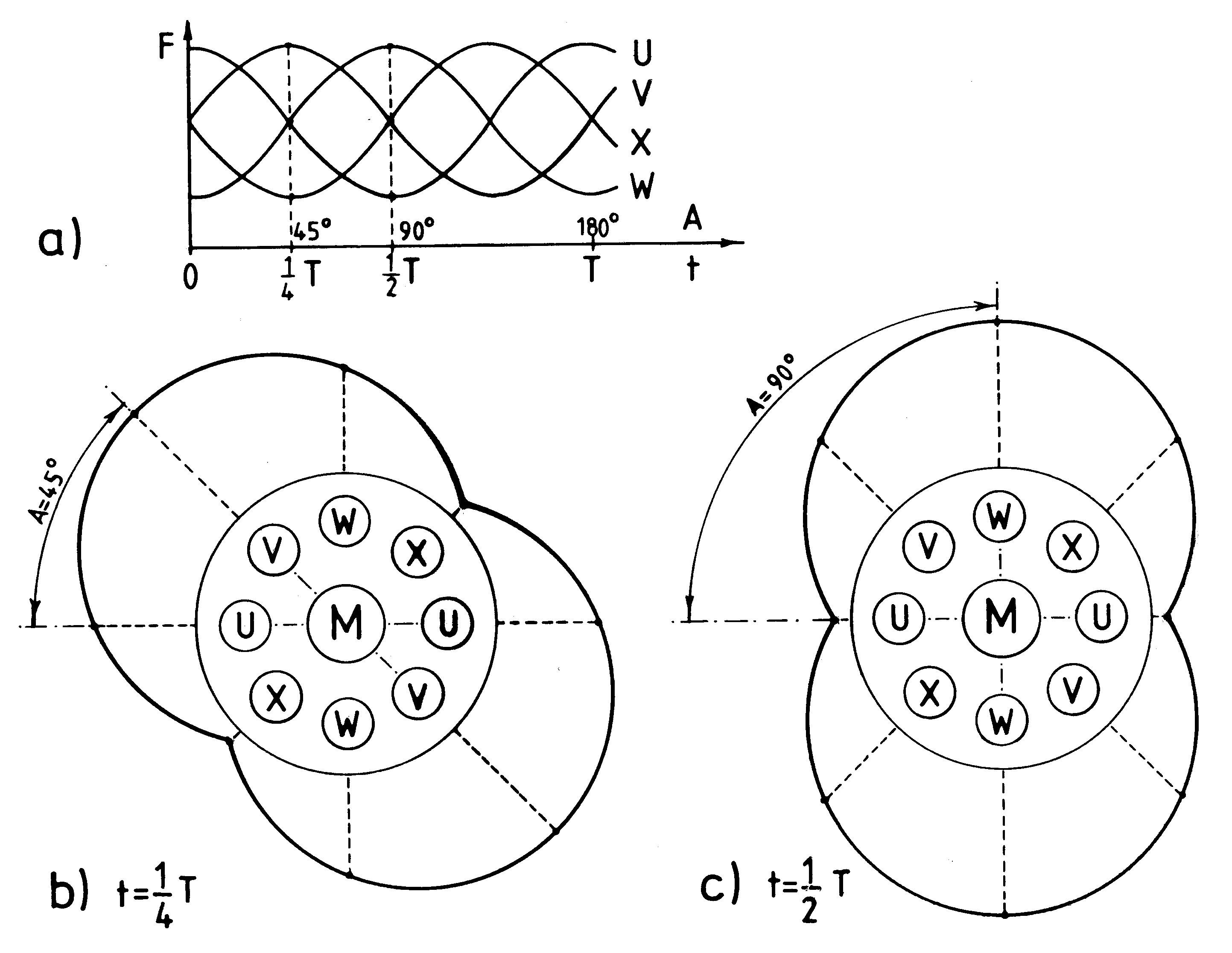 [2e] Figure G31: principles involved in converting field pulses from side propulsors into a Magnetic whirl. [2e] Figure G31: principles involved in converting field pulses from side propulsors into a Magnetic whirl.
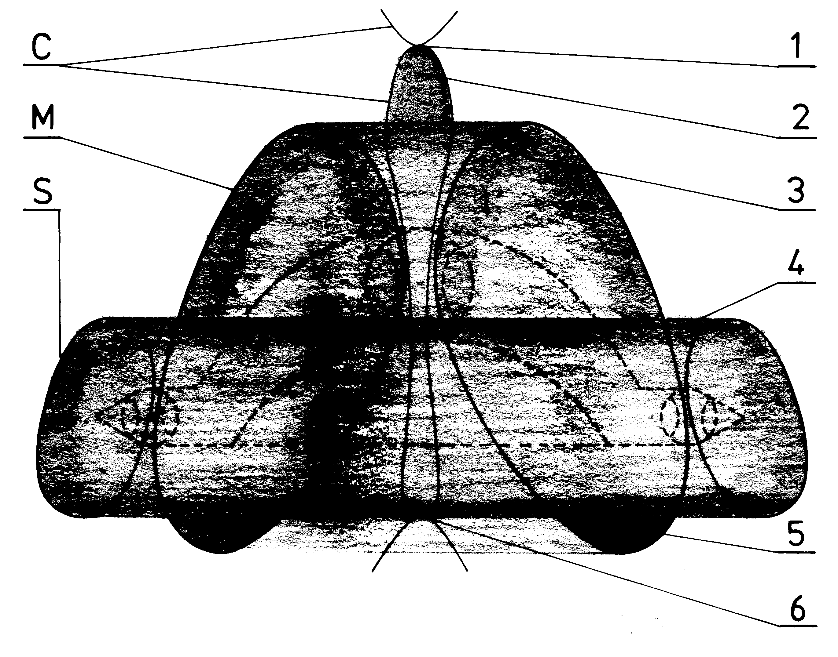 [2e] Figure G32: An example of the "ionic picture of a whirl". [2e] Figure G32: An example of the "ionic picture of a whirl".
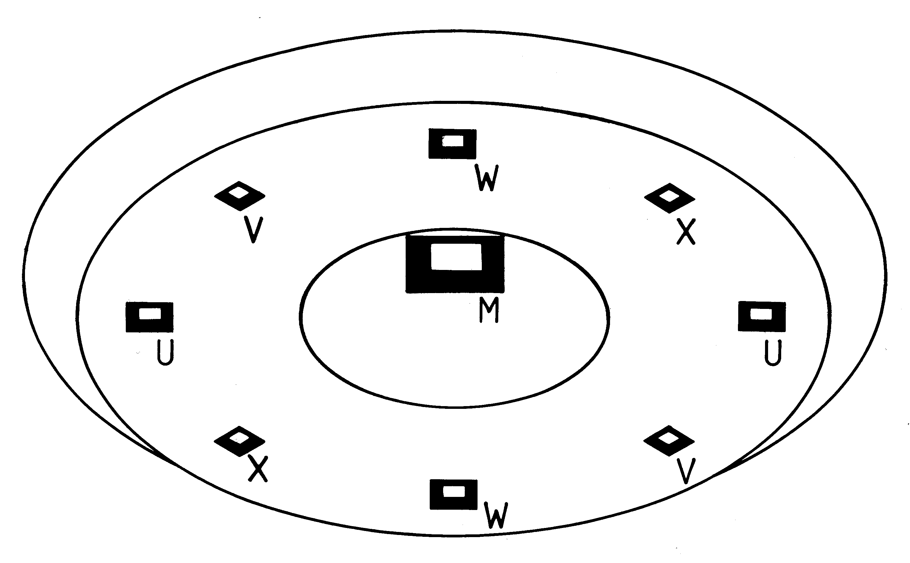 [2e] Figure G33 (a): Visibility of propulsors in K3 type Magnocraft. (a) The upward view. [2e] Figure G33 (a): Visibility of propulsors in K3 type Magnocraft. (a) The upward view.
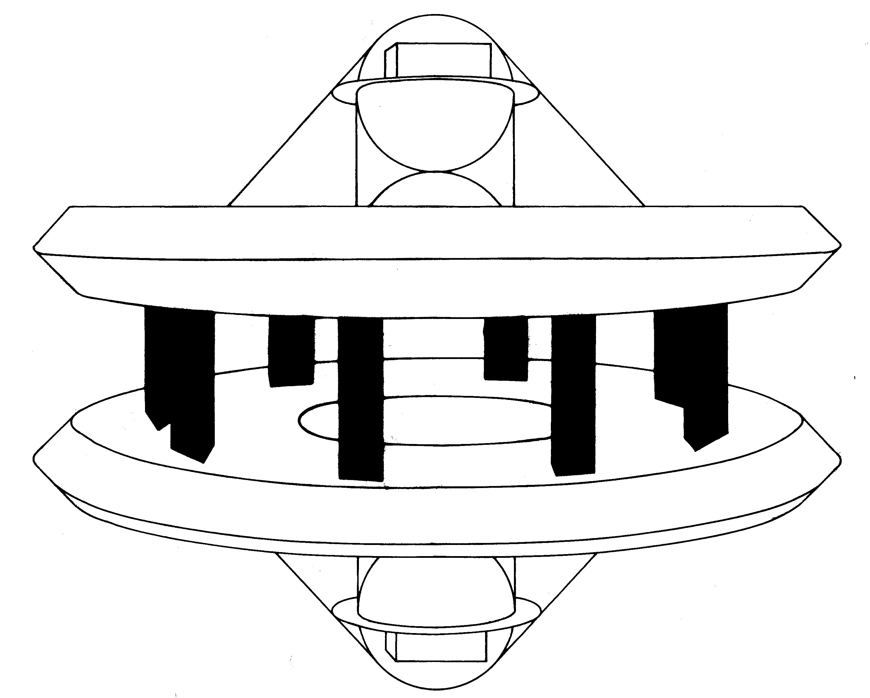 [2e] Figure G33 (b): Side view of a detached configuration. [2e] Figure G33 (b): Side view of a detached configuration.
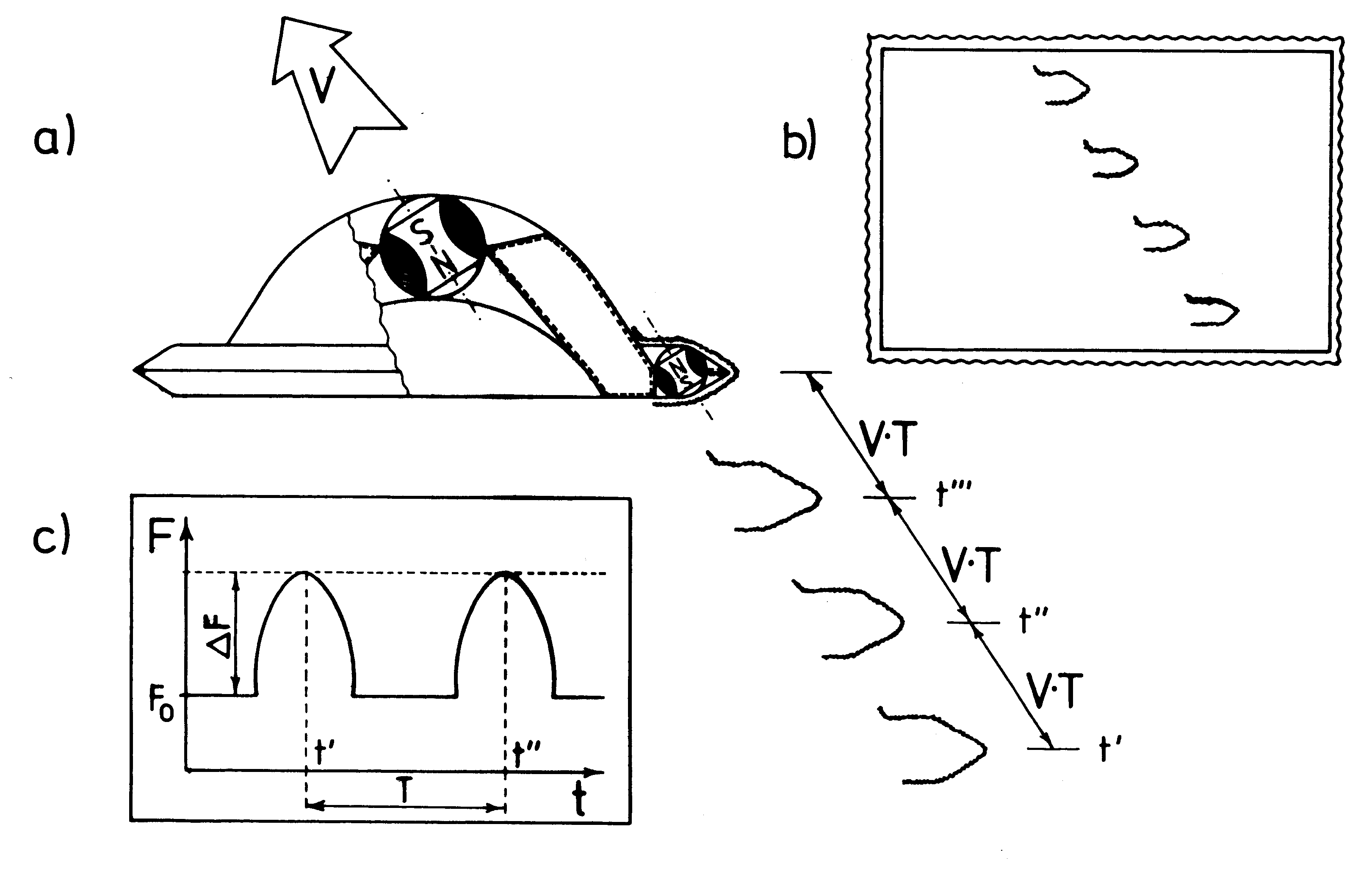 [2e] Figure G34: Multiple images of glowing magnetic circuits formed by a fast moving Magnocraft. [2e] Figure G34: Multiple images of glowing magnetic circuits formed by a fast moving Magnocraft.
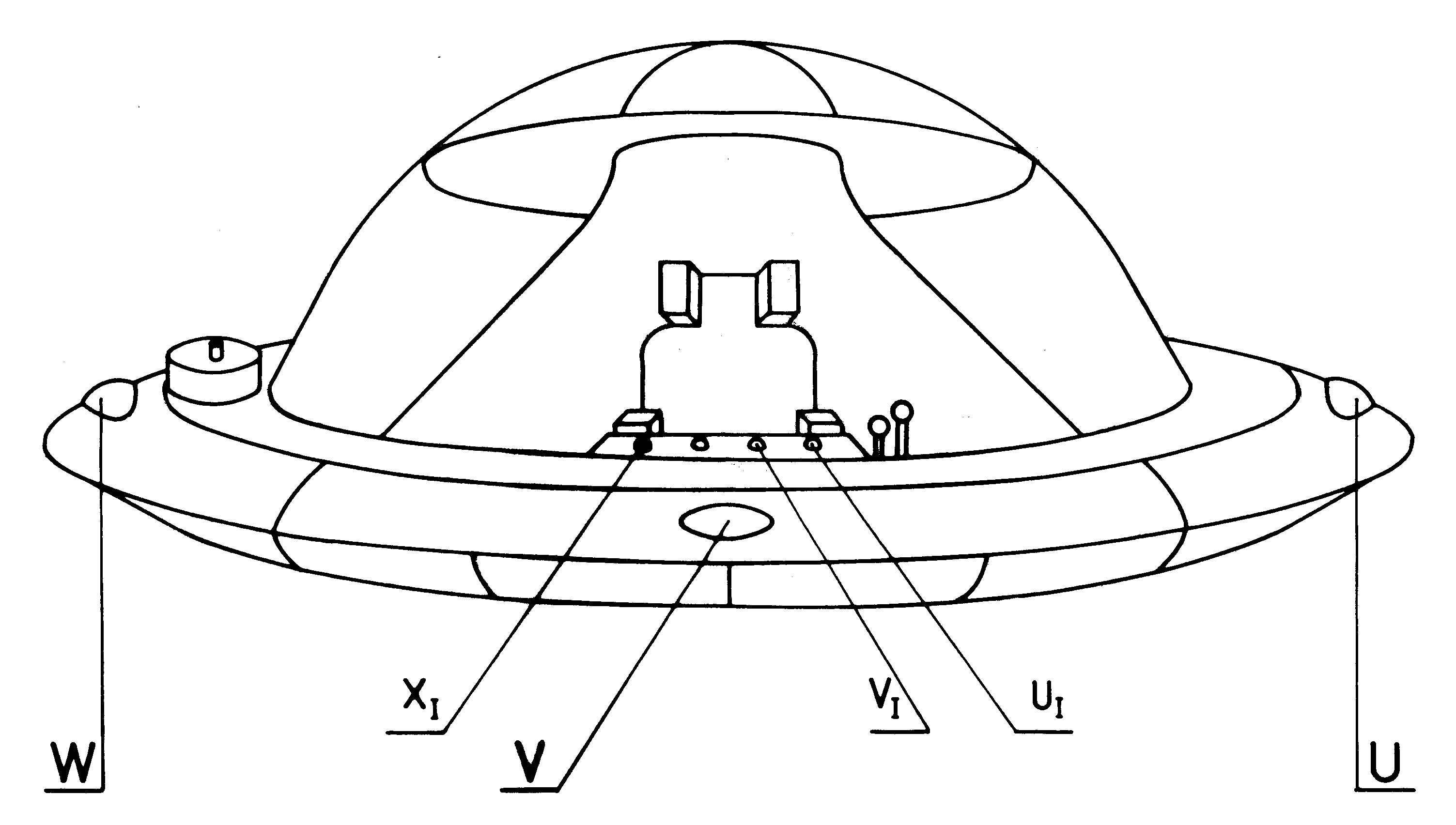 [2e] Figure G35: The SUB system of position lamps in the Magnocraft. [2e] Figure G35: The SUB system of position lamps in the Magnocraft.
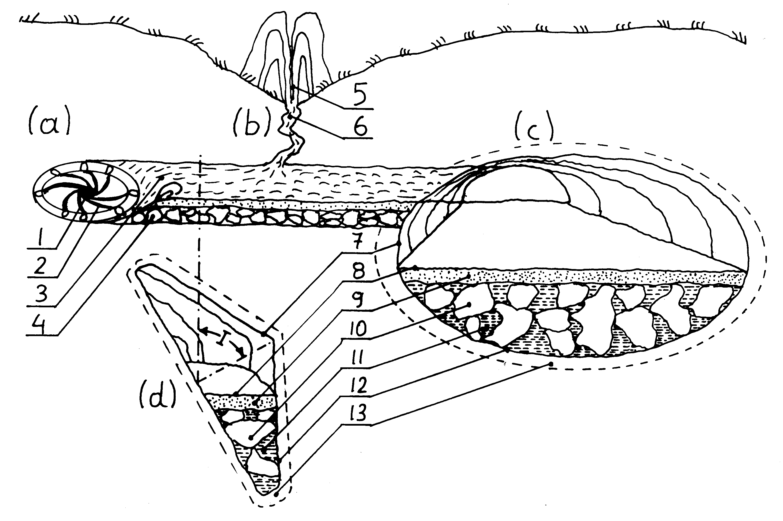 [2e] Figure G36: The illustration of pinciples of forming underground tunnels by UFOs. [2e] Figure G36: The illustration of pinciples of forming underground tunnels by UFOs.
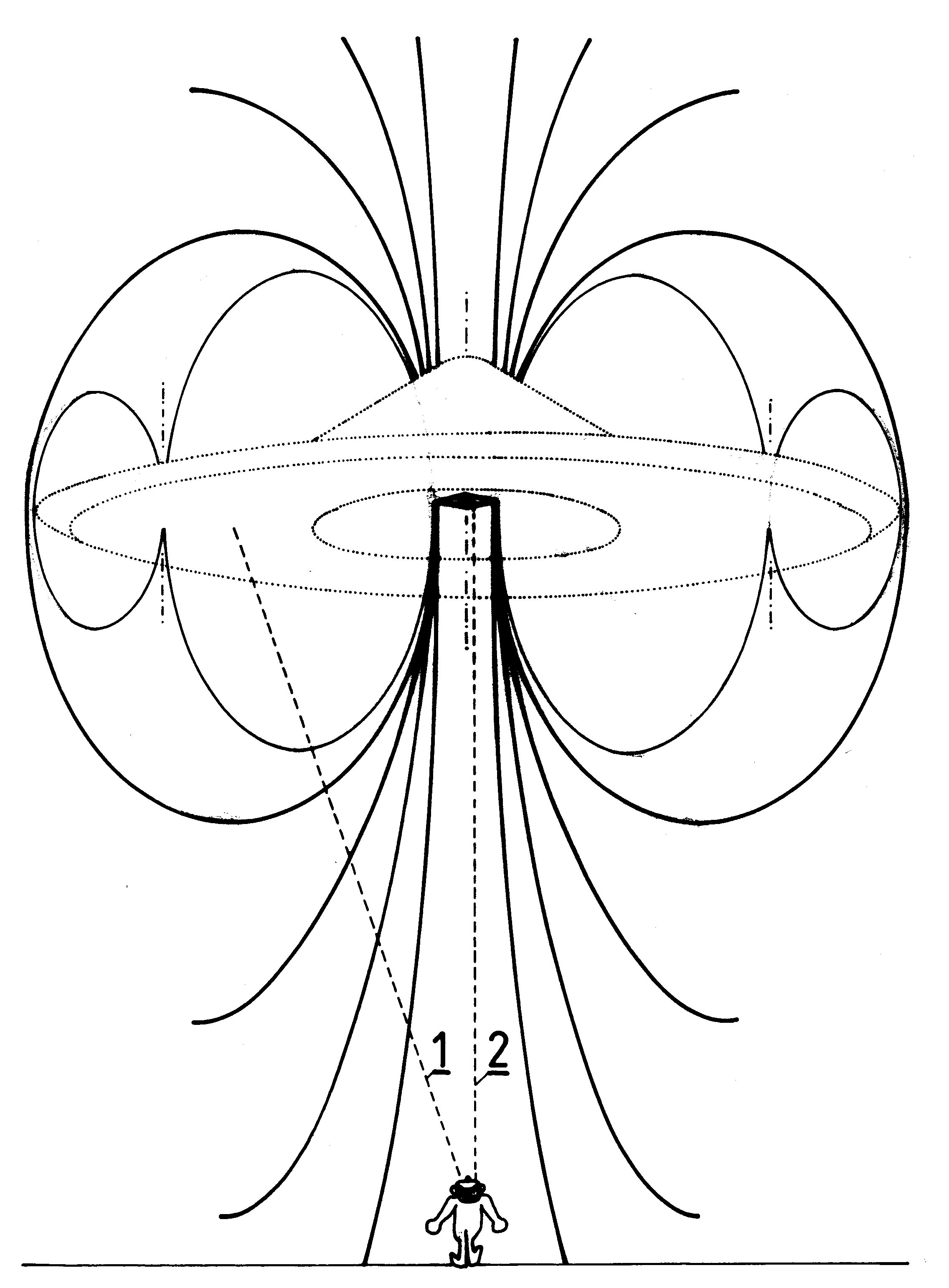 [2e] Figure G37: The explanation for the magnetic lens effect in ascending Magnocraft/UFOs. It explains why only the outlet from main "twin-chamber capsule" is visible as shown in [2e] Figure L5. [2e] Figure G37: The explanation for the magnetic lens effect in ascending Magnocraft/UFOs. It explains why only the outlet from main "twin-chamber capsule" is visible as shown in [2e] Figure L5.
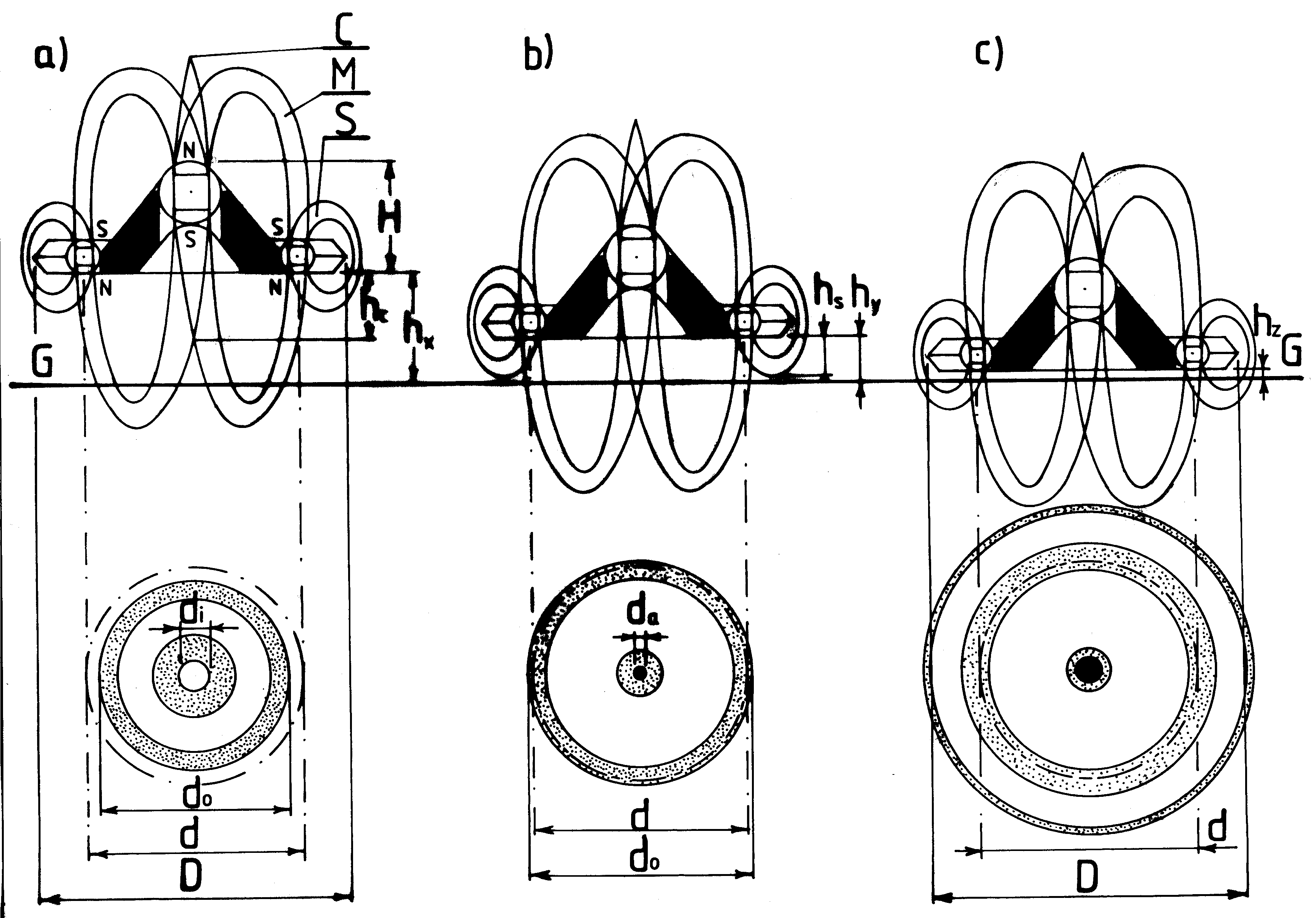 [2e] Figure G38: Shapes of marks left by a single Magnocraft (depending on the height of hovering). [2e] Figure G38: Shapes of marks left by a single Magnocraft (depending on the height of hovering).
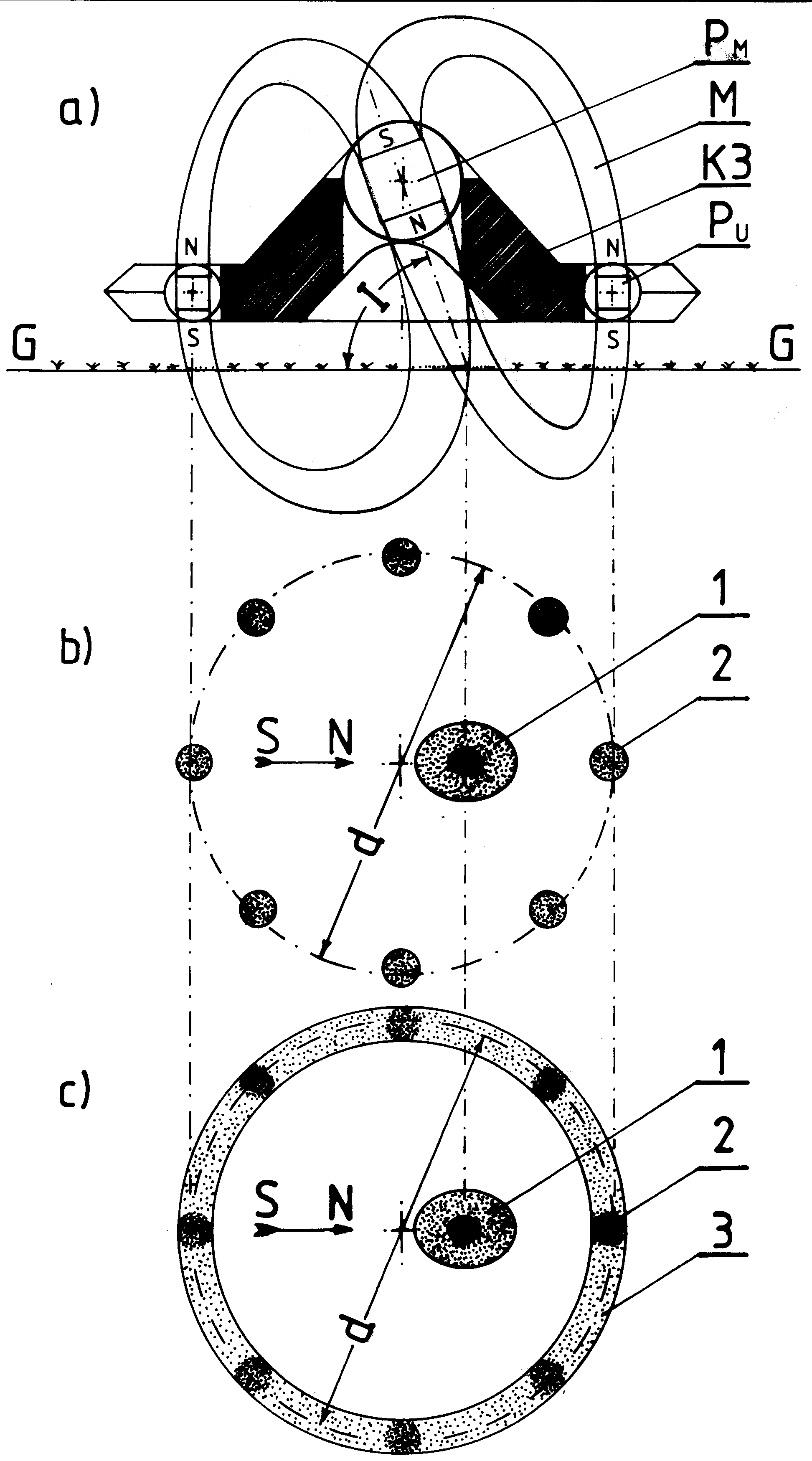 [2e] Figure G39: Typical marks in hovering close to the ground. [2e] Figure G39: Typical marks in hovering close to the ground.
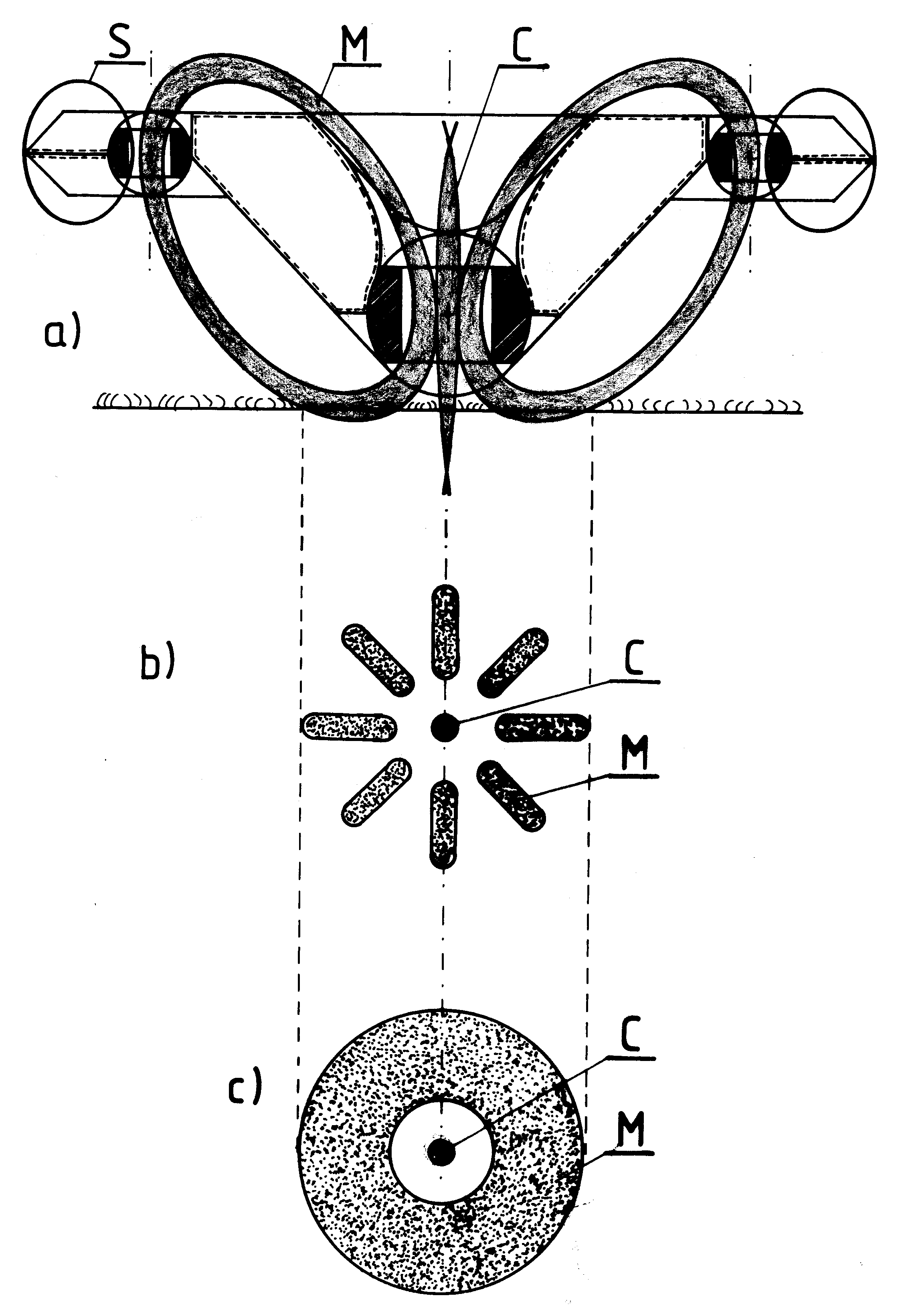 [2e] Figure G40: Landings scorched by an inverted Magnocraft. [2e] Figure G40: Landings scorched by an inverted Magnocraft.
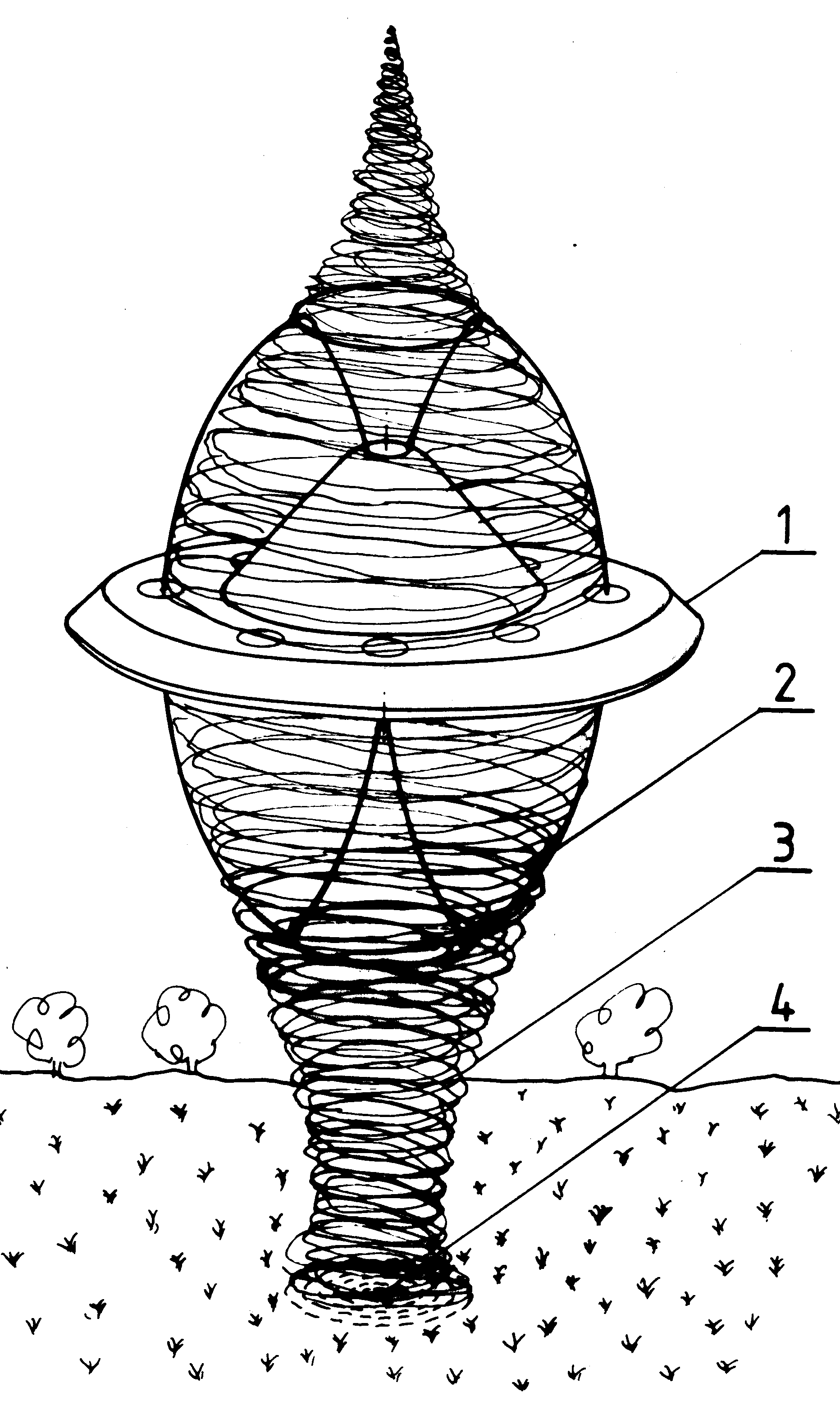 [2e] Figure G41: Plants swirled by circuits wehirling in the air. [2e] Figure G41: Plants swirled by circuits wehirling in the air.
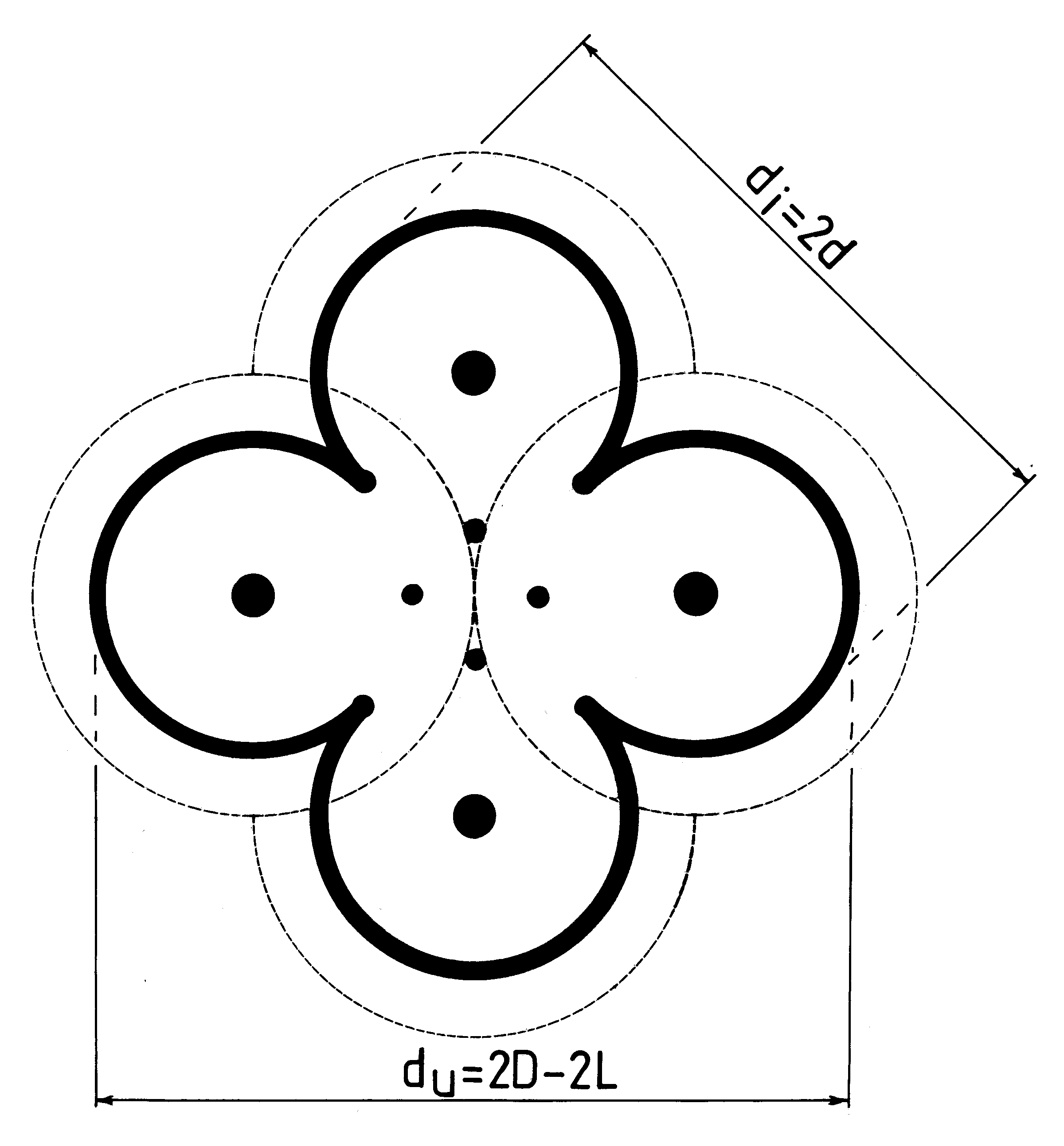 [2e] Figure G42 (a): Examples of landings formed by flying systems. (a) Landing of a single cell of a flying system. [2e] Figure G42 (a): Examples of landings formed by flying systems. (a) Landing of a single cell of a flying system.
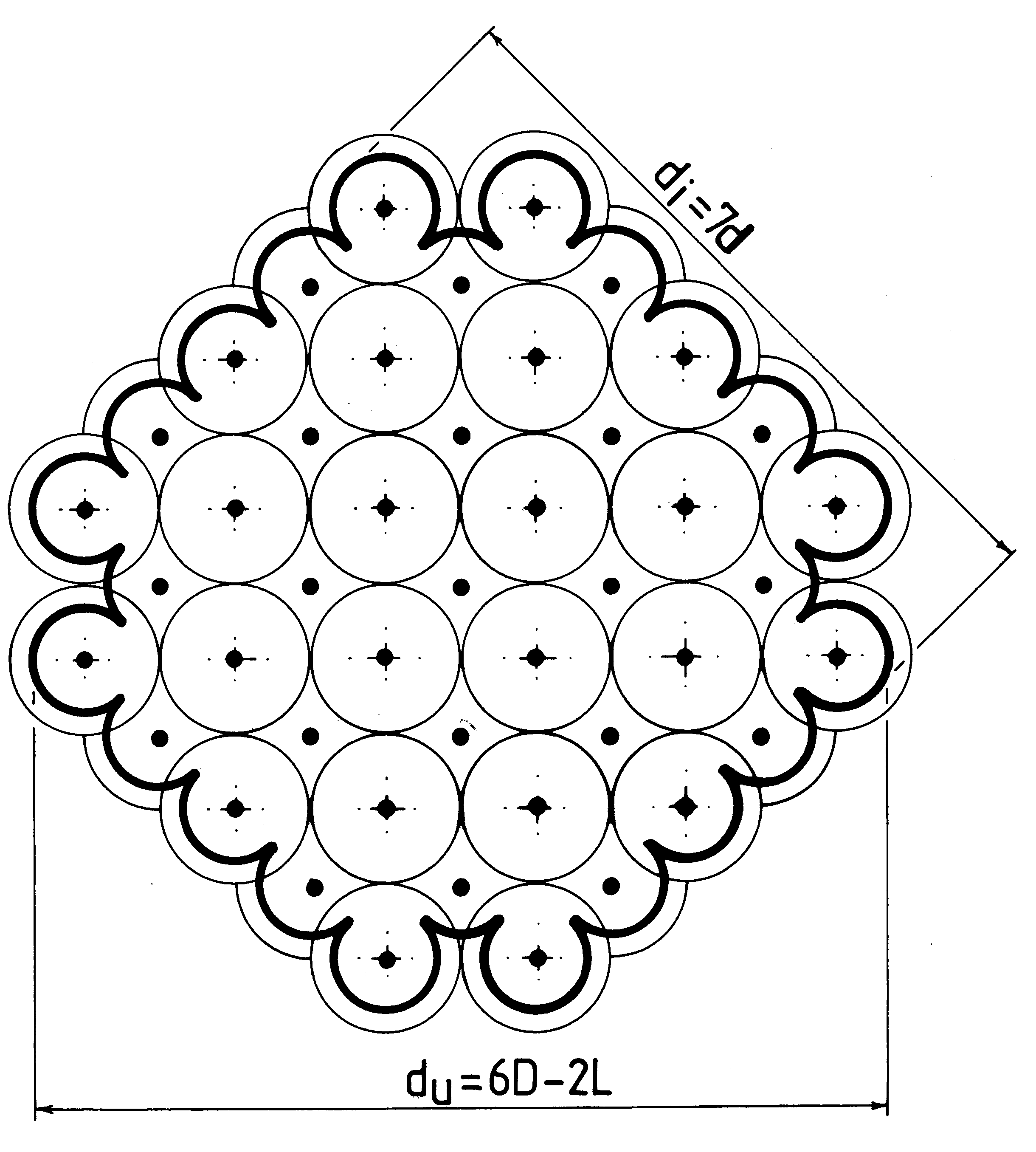 [2e] Figure G42 (b): Landing of a "platform" flying system. [2e] Figure G42 (b): Landing of a "platform" flying system.
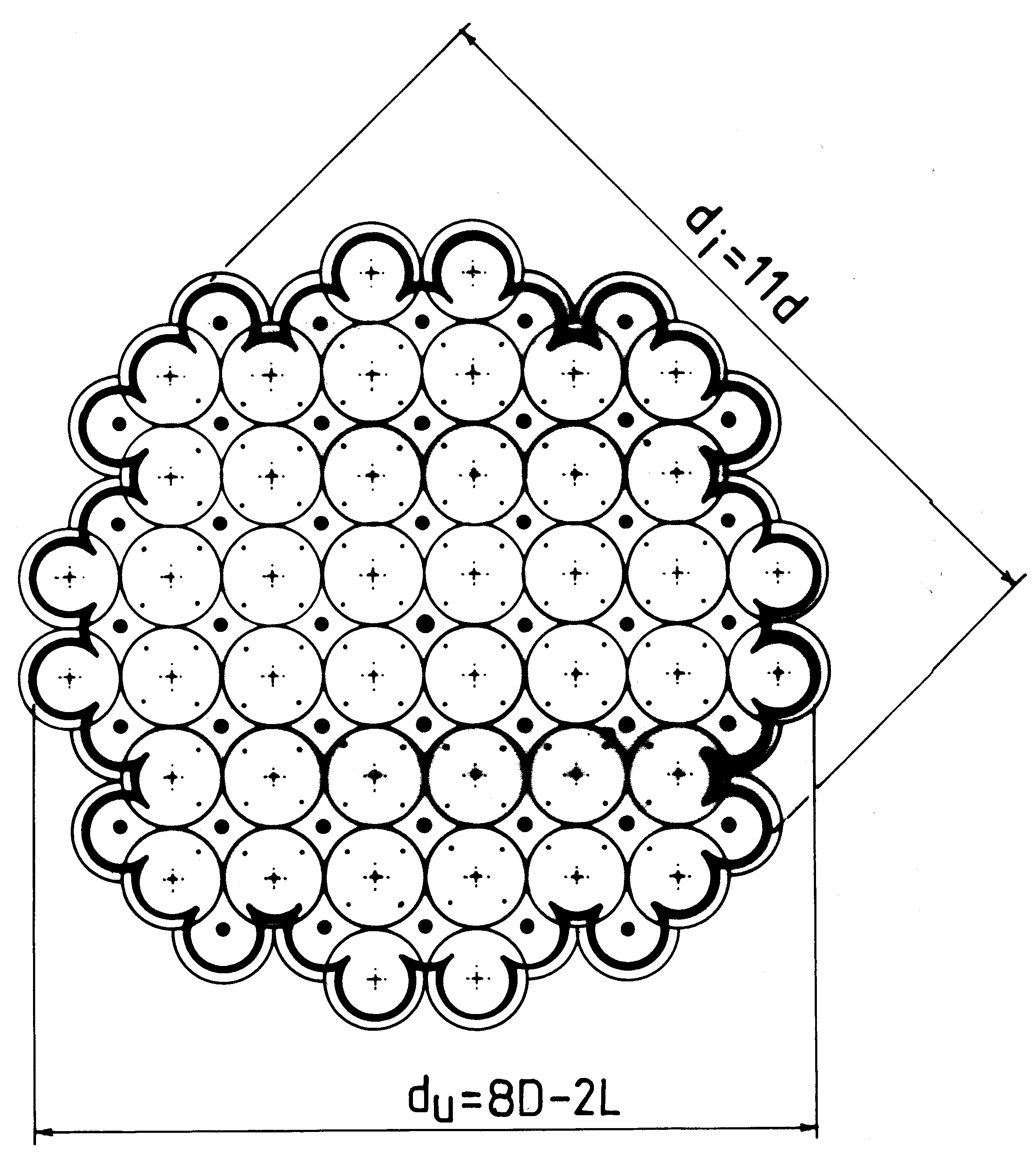 [2e] Figure G42 (c): Landing of a circular flying system. [2e] Figure G42 (c): Landing of a circular flying system.
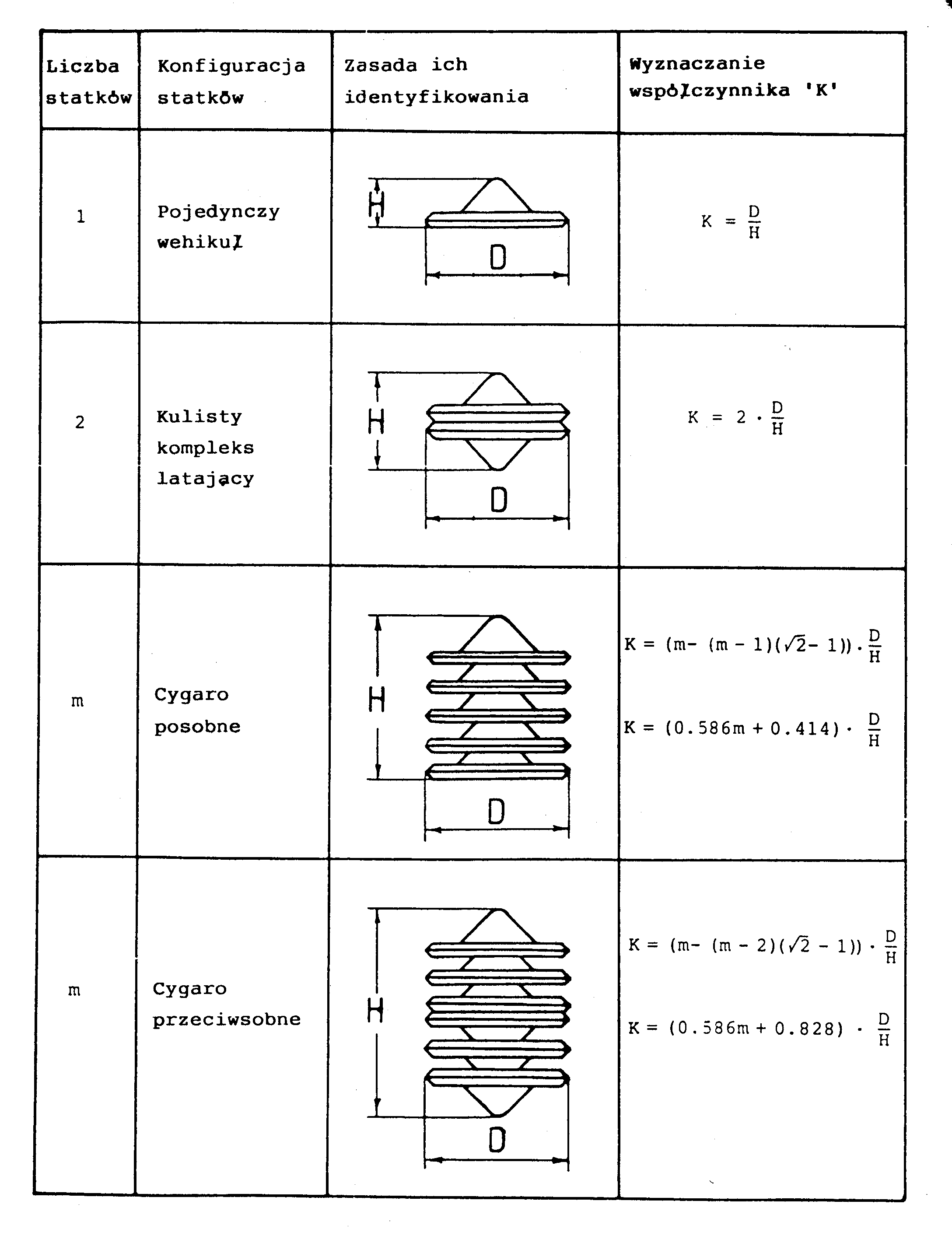 [2e] Table G2: The relationship of dimensions in flying complexes of Magnocraft (K versus D/H). [2e] Table G2: The relationship of dimensions in flying complexes of Magnocraft (K versus D/H).
Notice: because illustrations take a lot of computer memory,
and thus they download rather slowly and make the web page hard to scroll, there is
a practical limit to how many illustrations can be shown on a single web page. For
this reasons, all illustrations for [2e] are split into 4 separate web pages. This is just
one of these. Here are links to remaining web pages with these illustrations:
Links to illustrations of [2e] and to related texts:
Labels: The label "E" marks the web page with text and illustrations for the English-language version of this monograph.
Labels "1st, 2nd, 3rd Figures" mark the web pages with illustrations for subsequent volumes and chapters.
The label "T" marks the web page with the text of English-language version of this monograph
which is designed so as to load much faster because it does NOT show graphics at the loading
stage but only after the user clicks on subsequent Figures to display them.
The label "P" marks the web page with text of a Polish-language equivalent of this monograph.
Part #C:
Web pages which present various aspects of the
Oscillatory Chamber:
Various aspects of the Oscillatory Chamber
described in monograph [2e] that is disseminated
free of charge via this web page, are also
summarised on a number of totaliztic web
pages. Let us list here the most interesting
out of these:
oscillatory_chamber.htm - this web page summarises most vital information about the Oscillatory Chamber.
magnocraft.htm - explains the design of a starship which utilises Oscillatory Chambers for interstellar flights.
propulsion.htm - reveals applications of Oscillatory Chambers for purposes of transportation.
eco_cars.htm - describes, amongst others, declarations regarding help to build the Oscillatory Chamber.
immortality.htm - explain how Oscillatory Chamber provided people with a real access to immortality.
hurricane.htm - explains how Magnocrafts propelled by Oscillatory Chambers can control our weather.
tapanui.htm - illustrates what happens when the energy stored in Oscillatory Chambers is accidentally released.
Part #D:
Emails and contact details to the
author
of this web page:
Current email addresses to the author of
this web page, i.e. officially to
Dr Eng. Jan Pajak
while courteously to Prof. Dr Eng. Jan Pajak,
at which readers can post possible comments,
inquiries, or replies to questions which I ask on
my web pages, are provided on the web page
about me (Dr Eng. Jan Pajak).
That page also provides other commonly used
contact details to the author.
The author's right for the use of courteous
title of "Professor" stems from the custom that
"with professors is like with generals", namely
when someone is
once a professor, than he or she courteously
remains a professor forever. In
turn the author of this web page was a professor
at 4 different universities, i.e. at 3 of them,
from 1 September 1992 untill 31 October 1998,
as an "Associate Professor" from English-based
educational system, while on one university as
a (Full) "Professor" (since 1 March 2007 till
31 December 2007 - means at the last place
of employment in his professional life).
However, please notice that because of my
rather chronic lack of time, I reluctantly
reply to emails which contain JUST time
consuming requests, while simultaneously
they document a complete ignorance of their
author in the topic area which I am researching.
Therefore, if the reader sends a request to me,
I suggest to let me know somehow that he or
she actually went through the trouble of reading
my web pages and learning what these pages
try to say.
Part #E:
Copyrights © 2013 by Dr Jan Pająk:
Copyrights © 2013 by Dr Jan Pajak. All rights
reserved. The author of this web page, i.e.
Dr Eng. Jan Pająk, reserves for himself all
rights to internet web pages, illustrations,
and monographs which he authorises, and
also reserves for himself the intellectual
property of ideas of his authorship which
are presented in these publications.
Have the interesting reading about the Oscillatory Chamber which soon is to change our civilisation.
* * *
Date of starting this page: 2001
Date of the most recent update of this web page: 3 February 2013
(Check in "Menu 3" whether there is even a more recent update!)
|
 [2e] Figure G1: Principle of tilting the magnetic propulsor.
 [2e] Figure G2: The magnetic propulsion unit of the Magnocraft.
 [2e] Figure G3: Two alternative flight postions of the Magnocraft: upright and inverted.
 [2e] Figure G4: A side view of the Magnocraft and UFO type K3.
 [2e] Figure G5: The Magnocraft type K3 cross-section that shows the design and main features.
 [2e] Figure G6-#1: Flying complexes (cigar shaped)of UFOs and Magnocraft.
 [2e] Figure G6-#2: Semi-attached configuration.
 [2e] Figure G6-#3: Detached configuration.
 [2e] Figure G6-#4: A carrier platform (a mother ship).
 [2e] Figure G6-#5: A flying system of UFOs and Magnocraft.
 [2e] Figure G6-#6: A flying cluster of several UFOs and Magnocraft.
 [2e] Figure G7: A spherical complex of K3 type Magnocreaft.
 [2e] Figure G8 (a): A "stacked cigar-shaped flying complex" composed of six Magnocraft/UFOs type K6.
 [2e] Figure G8 (b):
  [2e] Figure G9: A double-ended cigar shaped flying complex.
 [2e] Figure G10 (a): Example of a "fir tree" shaped flying complex.
 [2e] Figure G10 (b): Side view.
 [2e] Figure G11: A very simple semi-attached configuration of K3 type Magnocraft.
 [2e] Figure G12: A "flying necklace" semi-attached configuration.
 [2e] Figure G13 (high): An example of K7 detached configuration.
 [2e] Figure G13 (low): Vertical cross-section shopwing the location of propulsors.
 [2e] Figure G14: An example of a carrier platform.
 [2e] Figure G15: A "zig-zag" carrier configuration.
 [2e] Figure G16 (a): Examples of flying systems.
 [2e] Figure G16 (b): Flying system shaped as "flutes".
 [2e] Figure G16 (c): Flying system shaped as a "honeycomb".
 [2e] Figure G16 (d): Flying system shaped as a "platform".
 [2e] Figure G17: An example of a flying cluster composed of two spherical complexes type K6.
 [2e] Figure G18: Coupling through a detached configuration.
 [2e] Figure G19: Coupling through a semi-attached configuration.
 [2e] Figure G20: Force interactions acting in Magnocraft.
 [2e] Figure G21: A top view of one cell of flying systems.
 [2e] Figure G22 (a): Meshing of flanges in flying systems.
 [2e] Figure G22 (b): Two cigar of K6 type mutually mesched.
 [2e] Figure G22 (c): two cigar of K7 type mutually mesched.
 [2e] Figure G23: Equations describing shape and dimensions of the Magnocraft.
 [2e] Figure G24 (a-K3): Side outlines of eight types of Magnocraft.
 [2e] Figure G24 (a-K4): K4 type.
 [2e] Figure G24 (a-K5): K5 type.
 [2e] Figure G24 (a-K6): K6 type.
 [2e] Figure G24 (b-K7): K7 type.
 [2e] Figure G24 (b-K8): K8 type.
 [2e] Figure G24 (b-K9): K9 type.
 [2e] Figure G24 (b-K10): K10 type.
 [2e] Figure G25: Methods of identifying the magnocraft's type.
 [2e] Figure G26: The creation of latitudinal thrust force.
 [2e] Figure G27: The "rolling sphere rule" for determing the flight direction.
 [2e] Figure G28: The counteracting of the magnetic whirl.
 [2e] Figure G29: Magnetic circuits and magnetic whirl.
 [2e] Figure G30 (a): The spinning circuits of K6 type Magnocraft.
 [2e] Figure G30 (bc): Side view showing magnetic circuits.
 [2e] Figure G31: principles involved in converting field pulses from side propulsors into a Magnetic whirl.
 [2e] Figure G32: An example of the "ionic picture of a whirl".
 [2e] Figure G33 (a): Visibility of propulsors in K3 type Magnocraft.
 [2e] Figure G33 (b): Side view of a detached configuration.
 [2e] Figure G34: Multiple images of glowing magnetic circuits formed by a fast moving Magnocraft.
 [2e] Figure G35: The SUB system of position lamps in the Magnocraft.
 [2e] Figure G36: The illustration of pinciples of forming underground tunnels by UFOs.
 [2e] Figure G37: The explanation for the magnetic lens effect in ascending Magnocraft/UFOs.
 [2e] Figure G38: Shapes of marks left by a single Magnocraft (depending on the height of hovering).
 [2e] Figure G39: Typical marks in hovering close to the ground.
 [2e] Figure G40: Landings scorched by an inverted Magnocraft.
 [2e] Figure G41: Plants swirled by circuits wehirling in the air.
 [2e] Figure G42 (a): Examples of landings formed by flying systems.
 [2e] Figure G42 (b): Landing of a "platform" flying system.
 [2e] Figure G42 (c): Landing of a circular flying system.
 [2e] Table G2: The relationship of dimensions in flying complexes of Magnocraft (K versus D/H).